One way you can control the temperature of a soldering iron is with a microcontroller, using temperature feedback from the thermistor in the handle near the iron's tip. This Design Idea presents a soldering iron driver that does this using only analog components.
Critical points are how quickly the iron gets to the required temperature and how big the swings around the set temperature are. The simplest way to control temperature is with an on-off switch which switches the heater off at the set point. This approach however results in temperature swings which are often undesirable. A preferred option is a PID controller (Reference 1). The optimal algorithm is to apply full power until the set temperature is reached for the quickest heat-up, and then to apply exactly the amount of power that will sustain that temperature resulting in no temperature swings.
To test this concept, I purchased an inexpensive soldering iron replacement handle knockoff (branded Hakko 907) from a well known auction website. It is rated for 50 W at 24 V, and has a positive temperature coefficient (PTC) sensor with a resistance of approximately 120 Ω at 300°C, and a coefficient of approximately 0.16 Ω/K. An old laptop power supply of 19 V was used as it was available; considerations for changing to a 24 V transformer are discussed below.
A Wheatstone bridge is formed from RB1 and RB2 in the upper legs, and RSensor (the soldering iron PTC) and RTrim (the temperature adjust) in the lower. In practice, RTrim could be a resistor & pot in series, a selector switch with several trimmed temperature presets, or any other method of your choosing.
The output of the bridge is fed into U2, a high-gain op-amp subtractor (Reference 2). Following the recommendations in Reference 2, R8-R11 have a tolerance of 1% and were individually measured and selected to match as closely as possible. U1 forms a 1.4 Hz 25% pulse generator that periodically turns on Q1, which in turn energizes the bridge with the full 19 V power supply. The higher voltage improves the sensitivity to temperature changes. However, the overall resistance of the bridge is rather low, resulting in high current. The low pulse duty factor and R7 limit the power dissipated in the bridge and prevent any heating up which would adversely affect stability.
 |
|
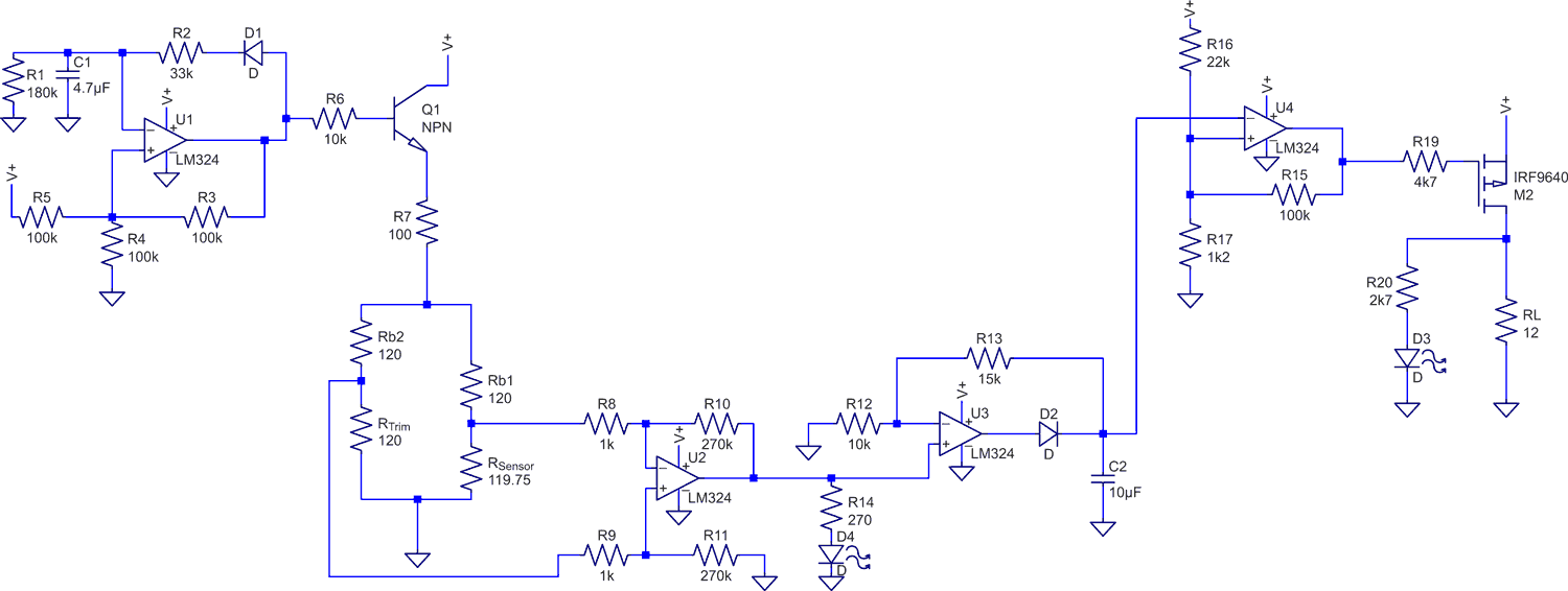
| Figure 1. | Feedback from the soldering iron's PTC temperature sensor controls the on-time vs the off-time of M2 to regulate the iron's temperature to the selected value. Most parts are not critical. A BC547 was used for Q1. |
U3 is an active peak-detector (Reference 4), and U4 is connected as an inverting Schmitt trigger (ST) with trip thresholds at about 5.8 V and 4.8 V (Reference 5). Referring to the waveforms of Figure 2, if the iron temperature is lower than the set point, C2 is charged up to a voltage higher than the ST threshold and remains so during the whole cycle while discharging through R12 & R13. The ST output stays low and turns on MOSFET M2, resulting in full power to the heater RL. If the iron temperature goes higher than the set point, the output of U2 is driven to ground, and the voltage of C2 is lower than the ST threshold, driving its output high and turning off M2.
 |
|
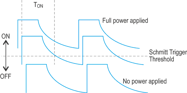
| Figure 2. | When the C2 voltage applied to the Schmitt Trigger U4 is entirely above or below the switching threshold the soldering iron is either full on or full off respectively for fast heating or cooling. When the iron temperature is close to the set point the C2 discharging voltage causes a variable pulse width to be applied to the iron for precise temperature control. |
Between these two extreme conditions, there exists a narrow range of approximately 0.3 Ω (defined by the value of the ST threshold, the overall gain of the subtractor and active peak detector, and the time constant of C2 and R12+R13) when, at some point during the cycle, the voltage across C2 will fall lower than the ST threshold and shut off M2 for the rest of that cycle.
The on-time of each cycle is inversely proportional to the rise in temperature – higher temperature works to increase the bridge voltage across RSensor, decreasing the charge voltage of C2, and hence the duration this voltage will take to discharge to a level below the ST threshold. This negative-feedback loop regulates the duty factor of the pulses to deliver the exact amount of heat for the temperature to remain constant.
If multiple temperature set-points are calibrated, there is no non-linearity of the temperature coefficient of the sensor to take into account. This results in high accuracy of each setting. The temperature at the tip stabilizes within 60-90 seconds after the “pulsing” mode has started, with no measurable swings. This delay is due to thermal lag in the soldering iron itself, as the PTC sensor is within the heating element and not at the tip where the temperature was measured. Another more immediate and sensitive indication of temperature stability is the flickering of the "Cold" LED D4, which flashes brightly when the iron temperature is lower than the set-point and is barely visible when the set-point is reached. D3 ("Heat") flashing indicates that the set-point has been reached and the circuit is metering out the needed quantities of heat.
Here’s a video of the circuit in operation. You can see (especially at the lower temperature) how power is applied irregularly to the soldering iron. Since everything in the circuit is powered by 19 V, VGS applied to M2 is close to the limit of 20 V when U4 pulls to ground. If you use a different MOSFET or want to increase the supply voltage to 24 V, make sure the maximum gate-source voltage of your MOSFET is not exceeded by using a zener or resistor divider.
References:
- PID, see PCB Heaven for a simple overview, and Galan, P., Enhanced temperature controller is both fast and precise, EDN March 1, 2001, pp 111-120 for a more formal treatment and improvements.
- Amplifiers for Signal Conditioning, Walt Kester, James Bryant, Walt Jung, figure 3.26
- LM324 data sheet
- Precision Active Peak detector
- A calculator for a single supply op-amp Schmitt trigger