Embedded Developer, September 2014
This application note describes how to digitize analog sensors and how to transmit their values wirelessly using the NXP configurable tiny logic gates 74AXP1G57 (see Appendix). The ability of these gates to be configured to work as inverting gates with Schmitt trigger inputs is used to build RC relaxation oscillators for both digitizing analog sensors and for producing the radio frequency (RF) signal required to transmit the sensor values wirelessly. A reference design for a wireless temperature sensor using amplitude modulated RF is provided. Implementation of wireless sensors as RFID tags is also mentioned as a means of building batteryless sensors.
Introduction
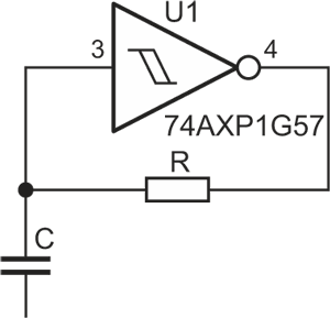
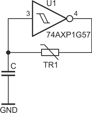
RC relaxation oscillators are very easy to implement using an inverting logic gate with Schmitt trigger inputs as shown in Figure 1.
 |
|
| Figure 1. | RC relaxation oscillator. |
The resistor R and capacitor C control the frequency of the oscillator, increasing the value of either R or C decreases the frequency of oscillation. Table 1 shows the frequency of oscillation of the 74AXP1G57 gate with various values of R with C fixed at 22 pF. Analog sensors are devices which have a physical property that is dependent on one or more (ideally only one) physical parameters.
For example, a thermistor is a device which has a resistance that changes with temperature; an electret microphone has a capacitance that changes with air pressure; a relative humidity sensor has a capacitance that changes with the amount of moisture in the air. The dependence of the oscillation frequency of a relaxation oscillator on the values of R and C is used to produce a frequency that varies with the varying values of resistance or capacitance of an analog sensor (and thus convert the analog sensor into a digital one) and to set the frequency of the RF signal used to transmit the sensor value.
Digitizing Analog Sensors
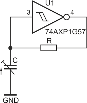
An analog sensor which behaves as a variable resistor or capacitor as described above can be easily digitized by replacing the resistor (if the sensor behaves like a resistor) or the capacitor (if the sensor behaves like a capacitor) in the RC relaxation oscillator of figure 1 with the analog sensor (shown in Figures 2a and 2b).
 |
 |
|||
| Figure 2a. | Resistive sensor. | Figure 2b. | Capacitive sensor with C fixed at 22 pF. |
|
Note:
Unused input pins must be tied high/low as described in the datasheet. For resistive sensors, choose C to obtain a suitable frequency of oscillation. For capacitive sensors, chose R to obtain a suitable frequency of oscillation.
If it is desired to encode the analog sensor as a variable duty cycle signal the circuit in Figure 2c can be used. As wired, the resistive sensor controls the high part of the signal while resistance R controls the low part of the signal.
 |
|
| Figure 2c. | Duty cycle encoding. |
A Simple Wireless Sensor
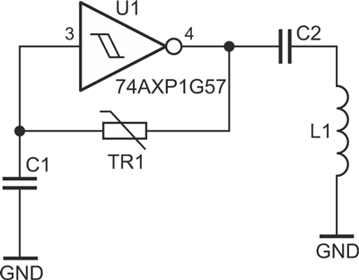
By carefully choosing the values of R and C an oscillator can be built to generate a signal at a desired frequency. If the chosen frequency is high enough it can be transmitted wirelessly to a radio receiver. Furthermore, if the value of the analog sensor is used to modulate the signal, the radio receiver can then retrieve the value of the analog sensor from the received signal. Figure 3 shows a very simple circuit that both digitizes the value of an analog sensor (thermistor) and transmits its value using a frequency modulated (FM) radio signal.
 |
|
| Figure 3. | FM temperature tensor. |
Note:
1) All unused input pins must be tied as described in the datasheets.
2) If using the NXP evaluation board for the 74AXP1G57 ensure pull-down resistor on pin 3 is removed.
If the value of C is set at 22 pF and a thermistor (TR1) is chosen with a nominal value of 18 kohm, the oscillator will generate a signal at a frequency of about 1.9 MHz (see Table 1). As the resistance value of the thermistor varies with temperature the frequency of oscillation will also vary, thus generating a radio signal at 1.9 MHz that varies in frequency with temperature changes. The frequency deviation caused by changes in the value of TR1 can be controlled by adding a suitable resistance in series with TR1. The value of C may have to be adjusted to generate a frequency in the range desired. For 1.9 MHz, C2 is 100 pF and L1 is made with 55 turns of enameled copper wire on a ferrite rod 10 cm long. C2 and L1 can be adjusted to optimize the range of the signal. Unfortunately, while this FM wireless sensor is simple and cheap to build, a radio receiver to recover the sensor value is much harder. The following sections will examine how to build amplitude modulated (AM) wireless sensors and a suitable simple radio receiver to recover sensor values.
AM Wireless Sensors
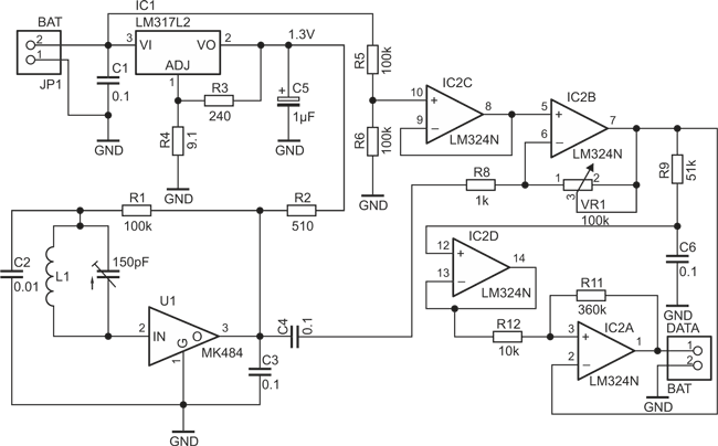
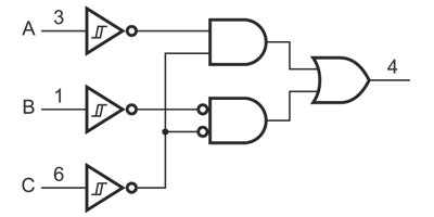
To put it all together, this section describes a reference design to implement an AM wireless temperature sensor. A 100 k thermistor is used as the analog temperature sensor. A frequency of about 1.9 MHz is chosen as the radio carrier frequency as this frequency is well within the capabilities of the 74AXP1G57 device (and within the capabilities of the cheap radio receiver that is described in the next section). The thermistor is used together with a 0.02 µF capacitor and a 4AXP1G57 configured as an inverter with Schmitt trigger input to generate a frequency of about 11 kHz. The 1.9 MHz carrier frequency is generated using a 22 pF capacitor and an 18 kohm resistor with a second 74AXP1G57 device configured as a NAND gate with Schmitt trigger inputs. The noninverting input of the NAND gate is used to build the 1.9 MHz carrier frequency while the inverting input of the NAND gate is connected to the sensor oscillator which turns on and off the carrier oscillator, thus amplitude modulating the carrier. Please refer to the circuit in Figure 4.
 |
|
| Figure 4. | AM wireless temperature sensor. |
Note:
1) All unused input pins must be tied high/low as described in the datasheets.
2) If using the NXP evaluation board for the 74AXP1G57 ensure pull-down resistors on pin 3 and pin 6 are removed.
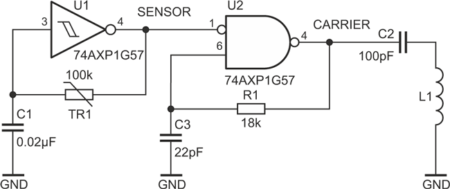
The following waveform is the signal (sensor) produced at the output of the first AXP device (U1, pin 4):
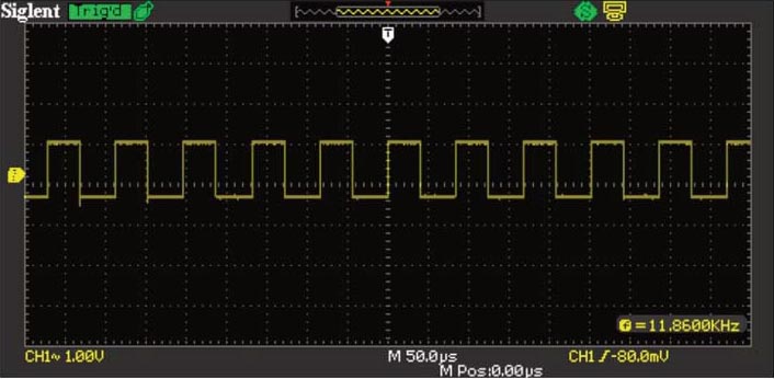
When pin 1 of U2 is connected to ground instead of the the U1 pin 4, the following waveform is obtained:
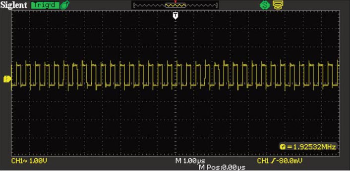
With pin 4 of U1 connected to pin 1 of U2 as shown in the circuit of Figure 4 but with L1 disconnected, the following waveform results:
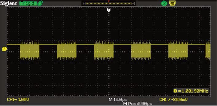
Connecting L1 to capacitor C2 results in the following: (The blue waveform is the sensor signal, for reference)
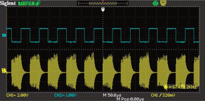
Notice that the amplitude of the AM waveform is about six times as large when compared with the waveform without L1 and C2 connected. Adjusting the values of L1 and C2 may result in higher amplitudes and thus higher RF range.
Simple and Cheap AM Radio Receiver
If the carrier frequency is chosen to be between 525 kHz and 1.6 MHz it may be possible to use a standard medium wave broadcast radio receiver to retrieve the sensor oscillation frequency from the carrier (as an audio signal). As the carrier frequency used in the reference design of section 5 is beyond the 1.6 MHz limit of a standard medium wave broadcast radio receiver, the receiver and decoder circuit in Figure 5 is proposed.
 |
|
| Figure 5. | AM radio receiver and data recovery circuit. |
Although the circuit contains significantly more components than the sensor radio transmitter, the circuit is very simple. U1 is the main component of the radio receiver as it provides the radio receiver functionality required. L1 and the variable capacitor form a tuned circuit to select the carrier frequency of the sensor carrier (1.9 MHz). The output of U1 is the sensor signal that was amplitude modulated on the 1.9 MHz carrier.
The LM317 voltage regulator (IC1) is configured to provide 1.3 V to power the MK484 radio receiver device (U1). As the signal coming out of the radio receiver (U1) may be quite weak, it is amplified by IC2B with VR1 acting as amplification control.
The sensor signal is recovered using a technique called “data slicing”. Resistors R5 and R6 with IC2C provides a reference point (half the input voltage injected at JP1) about which IC2B can amplify the sensor signal.
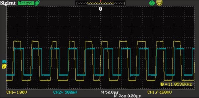
The amplified sensor signal is fed to one input of the comparator built around IC2A. The average value of the amplified sensor signal obtained using R9 and C6 is buffered by IC2D and sent to the other input of the comparator, the output of which is the retrieved sensor signal used to amplitude modulate the carrier as can be seen in the waveform in Figure 6.
 |
|
| Figure 6. | Recovered sensor signal. |
In Figure 6, the blue waveform is original sensor signal. Yellow waveform is recovered sensor signal.
Power Solutions for the Wireless Sensor
In the sections above no mention was made about supplying power to the NXP 74AXP1G57 device. Note that as a radio transmitter is a device that converts electrical energy into radio energy, a suitable power source must be selected to achieve the radio range required. A range of about 30 cm was achieved with an old alkaline cell with a terminal voltage of 1.3 V.
While the prototyping work described above was done using a partially depleted 1.5 V alkaline cell as the power source, the low voltages and very low power requirements of the NXP device make viable power solutions which are not battery based.
A number of energy harvesting solutions can be considered, such as scavenging power from RF energy from mobile phone towers or radio and TV broadcast stations. Taking advantage of extremely low power requirements of the 74AXP1G57 device, a viable option is to implement wireless sensors using the radio frequency identification (RIFD) tag model. A sensor is built as per Figure 2a or 2b with its power source consisting of circuitry to charge a capacitor from a radio signal, similarly to a RFID tag. When the value of the sensor needs to be read, the reading terminal generates a radio signal which is used by the sensor to power on and which it then modulates as the sensor oscillates. The modulation of the radio signal is detected and decoded by the terminal.
In Conclusion
The circuits described above were prototyped using the NXP Evaluation Board for the 74AXP1G57 logic gate. Without the evaluation board it would have been very hard to experiment with these tiny devices without first making a printed circuit board to mount them.
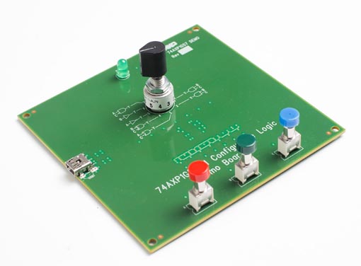 |
| NXP demo board for configurable logic device 74AXP1G57. |
Appendix. The 74AXP1G57
General description
The 74AXP1G57 is a configurable multiple function gate with Schmitt-trigger inputs. The device can be configured as any of the following logic functions AND, OR, NAND, NOR, XNOR, inverter and buffer. All inputs can be connected directly to VCC or GND. This device ensures very low static and dynamic power consumption across the entire VCC range from 0.7 V to 2.75 V. This device is fully specified for partial power down applications using IOFF. The IOFF circuitry disables the output, preventing the potentially damaging backflow current through the device when it is powered down.
Features and benefits
- Wide supply voltage range from 0.7 V to 2.75 V
- Low input capacitance; CI = 0.5 pF (typical)
- Low output capacitance; CO = 1.0 pF (typical)
- Low dynamic power consumption; CPD = 2.7 pF at VCC = 1.2 V (typical)
- Low static power consumption; ICC = 0.6 µA (85 °C maximum)
- High noise immunity
- Latch-up performance exceeds 100 mA per JESD 78 Class II
- Inputs accept voltages up to 2.75 V
- Low noise overshoot and undershoot < 10 % of VCC
- IOFF circuitry provides partial power-down mode operation
- Multiple package options
- Specified from –40 °C to +85 °C
| Table 1. | Resistance-frequency dependence. | ||||||
|
|||||||