Marko Kannisto, Maxim Integrated
Application Note 5147
There are thermal issues to consider. With a 12 V supply voltage and a 4 Ω load, the amplifier's efficiency with 20 WRMS output power is approximately 85%. We can calculate how much power is dissipated in the amplifier with the following formula:
![]()
The MAX98400A is in 36-pin TQFN package, which means that an external heatsink cannot be used very easily. An alternate way to remove excess heat from the amplifier is to connect the exposed pad located underneath it to the PCB's copper plane with multiple vias. To lessen any further concerns about temperature, the MAX98400A has built-in thermal overload protection.
Consequently, when this Bluetooth audio system is used in a very warm ambient temperature and the audio amplifier is delivering its highest possible output power, nothing will be damaged or destroyed.
Assembling the System
 |
|
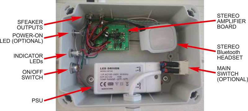
| Figure 7. | The system assembled in an enclosure. |
The system is finally assembled into an industrial waterproof enclosure sized 120 mm × 160 mm. Figures 7 and 8 show the assembled and fully functional system with all required building blocks.
 |
|
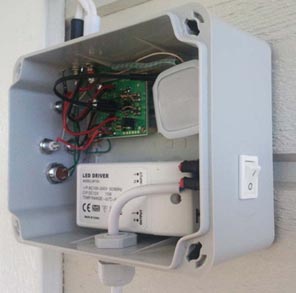
| Figure 8. | System enclosure viewed on an outdoor wall. |
Now Make Some Music
This article has explained how to make an inexpensive wireless Bluetooth stereo audio system for outdoor use. Now it is time to mount the system enclosure on a hard surface like a wall, connect the speakers, and plug mains voltage into the audio system. Establish a Bluetooth connection and you are ready to rock and roll!
Appendix 1
Things to Consider
Audio Amplifier
There are always electromagnetic interference (EMI) issues to consider when using a Class D audio amplifier in a design. If your system needs long speaker cables (over 1 m), it would be good to use a ferrite bead mounted to the speaker cable to reduce radiated emissions.
 |
|
| Figure 9. | Maxim Class-D waveforms with and without active emissions limiting. The over- and undershoots seen on the data at the right are sources of radiated emission. |
Additionally, stereo amplifiers with Maxim's active emissions limiting technology make it easier to comply with EN55022B EMI limits. Active emissions limiting greatly reduces radiated emissions. The technology optimizes the output FET gate transitions, reducing over- and undershoots dramatically, to provide very good EMI performance without degrading the audio performance (Figure 9).
Stereo Bluetooth Headset
There are many different layouts when assembling the PSU, stereo Bluetooth headset, audio amplifier, switches, and LEDs into an enclosure. Make sure that no cables cross the headset's Bluetooth antenna, since that can reduce the Bluetooth range.
Also, do not mount the system very near other wireless transmitters, for example beside a WLAN router, because this those transmissions can interfere with the headset's reception.
Power-Supply Unit (PSU)
The amplifier in this design has a high 67 dB PSRR which eliminates the need for a tightly regulated power supply. Nonetheless, be sure to choose a PSU that has reasonably good output voltage regulation. This, in practice, means that one should not use the lowest-cost PSU available.
Indicator LEDs
Perhaps the hardest part of building this system is soldering wires to the LED indicator pads located on the Nokia BH-214 PCB. If you have any doubts about soldering these wires, change to an enclosure with a transparent front cover. In that case, the stereo Bluetooth headset would be mounted sideways to make indicator LEDs visible through the front cover. Now the LED indicators would not need to be removed from the PCB.
The wires for the On/Off switch and the wires to the battery pads still need to be soldered to the headset's PCB. That soldering job is much easier than soldering for the LED indicators.
The power-on LED is optional. If you choose to mount it, a series resistor must be used to limit LED current. Calculate the LED series resistor value with following:
![]()
When the LEDs are supplied from the 3.6 V LDO output and when the LED forward voltage is 1.8 V with, for example, an 8 mA LED current, then the series resistor would be:
![]()
Appendix 2
Trade-offs Between a Class D and Class AB Amplifier
This design uses a Class D audio amplifier for the reasons outlined above. Perhaps, however, you have a Class AB linear amplifier and want to use it in the design instead? The system will be much less efficient. A Class AB linear amplifier operating under same conditions will have approximately 50% less efficiency than the Class D device, meaning that there will be 10 W of dissipated (wasted) power in the amplifier. Therefore, a fairly large heatsink would be required for thermal protection.
When you consider how much power a Class AB amplifier would waste in this application, it is easier to understand why the term "RMS output power" is misleading. Assume that two amplifiers, a Class D and a Class AB amplifier, are delivering the same 20 WRMS output power. In our example, the MAX98400A will dissipate 3.5 W and a Class AB amplifier will dissipate 10 W. Thus, even when the RMS output power seems to be the same, the Class AB amplifier cannot deliver as much power to the speakers because it is wasting so much power. In the end, less power translates to considerably less sound.
Appendix 3
System Parts
A system part list is shown in Table 2.
| Table 2. | System Parts List. | ||||||||||||||||||||||||||||||||||||
|
|||||||||||||||||||||||||||||||||||||
Materials on the topic