I was trying come up with something impressive to write about, after having the blog dormant since July. I tossed around a lot of different ideas… Although I haven’t been writing, I’ve been dabbling in a number of different projects. None of them are really in a state I’m ready to write about. That brings me to something I saw a few months ago on MAKE. Bre and associates had constructed a simple 3 × 3 × 3 led cube, re-purposing a POV toy to drive the leds.
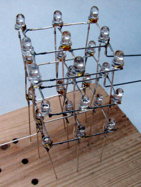
I figured this would be a good easy project I could finish in a day, so I drilled out a piece of pine board and set to soldering up some 3 mm leds. I wasn’t very careful, so the little matrices look kind of ugly, but it all works and you can’t see the wires in the dark!
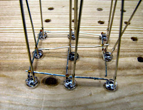
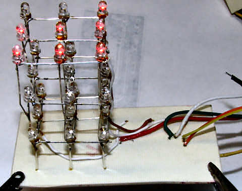
It didn’t take very long to toss three of these nine led matrices together. Assembling them into a twenty-seven led cube was a bit trickier. I used some gator clips to hold parts of the cube while I soldered it. Eventually I finished all the connections and had a passable cube with fairly even spacing.
Assembling the matrix is a pretty straight forward task. All you really do is tie all the cathodes together. Each matrix will become one row in the finished cube. Electrically, the cube is built as a 3 × 9 array, three rows and nine columns. You could probably build it the other way around, anode rows and cathode columns, but it is easier to sink a large current than source it. I think the MAKE: software only lights one led at a time, since they’re relying on the microcontroller to both source and sink current. My design is a bit different. The mcu sources current to each anode column, and N channel fets sink current for the entire row. The N channel is easily able to sink a few amps, so the cube can light an entire row at once without having to multiplex the individual leds.
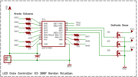
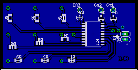
In order to keep the PCB layout simple, the connections are spread all over the place in terms of the registers inside the pic. It would have been cleaner to organize eight of the nine columns as a single 8bit register on the pic, leaving only one bit left over to deal with. Instead, I’ve created symbols for each column, and set them individually from 9bit numbers.
Each anode column is current limited by a 75 ohm resistor. The value chosen was rather arbitrary, since the leds have such a low duty cycle, a lower value would have afforded me more brightness when the cube is battery powered. I can tweak the brightness a bit in the software, changing the scan rate the rows are multiplexed at.
That’s pretty much it. I’ve found there’s not a lot you can do with only 3 × 3 × 3 and 1 color, but it’s still kind of fun. Trying to think in three dimensions while drawing the animation frames is kind of tricky. I started with excel, but that wasn’t very useful - I spent more time copy and pasting formulas than I did ‘drawing’. Luckily my buddy Dan helped me out with that. He whipped up an awesome little php script that lets you draw animations 27 leds at a time, and it formats the resulting numbers so I can copy and paste them right into the code.