Chris
Introduction
When I first started in the field of robotics, electronics and sensors I had always wanted to make my own robotic arm. The idea of being able to make such an advanced idea come to life out of simple parts found around the house was mind boggling to me. So inspite of that, I set out to prove to myself it was possible.
I went through several initial designs before I set my heart on the one that you see here. I feel this one is the simplest that I came up with and therefore the easiest to build. I still can't get over the It's made out of friggin' wood! factor of this design.
Purpose & Overview of this project
The goal of this project is to create a robotic arm that can move in most any direction like a humanoid arm. It should have grippers on the end that can grip trivial objects like a piece of paper or a pen/pencil. A simple design with as few moving parts as possible is important for this design because the arm will only be controlled by a PIC18F452. This potentially limits the ability to control the arm with smooth movements.
The Wooden Menace robotic arm should be made out of generally cheap household items (except the servos). The reason for this is to prove that such a design can and will work.
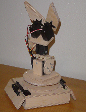
Wooden Menace
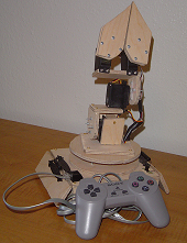
Wooden Menace with Controller
Parts List
-
Electrical Parts
- LM7805 5 V Voltage Regulator
- PIC18F452 Microcontroller
- Female RJ45 Connector
- (5) Hi-Tec 311 Standard Servos
- 20 MHz Oscillator
- SPDT Switch
- 1µF Capacitor
- 30 pin SIP
- 540 point Breadboard
- Solder
- Wire 24 AWG
- Wire 30 AWG (aka Wirewrap)
-
Hardware Parts
- Hobby Wood
- 8 small nails
- 5 minute E-poxy
- Fancy Door Hinge
- Plastic Sheet
-
Tools
- Wirewrap Tool
- Soldering Iron
- Laptop Computer
- MPLAB IDE (installed on Laptop)
- PIC Programmer
- Power Drill
- Hammer
- Jigsaw
- Sand Paper
Schematic
Schematic Overview
The hardware schematic for the wooden menace (robotic arm) is fairly straight forward. The PIC microcontroller has one control line feeding to each servo and it also connects to the RJ45 connecter. The RJ45 connector is used for getting input from the controller.
Click to enlarge
Schematic Specifics
-
Power Circuit
- The power circuit is just a 9 V Battery hooked up to the LM7805 with a 1uF capacitor hooked to output & ground of the LM7805 to keep a steady 5 V DC.
-
Servo Connections
- Each servo has 3 wires coming out of it. Power, Ground & Signal (PWM). Power & Ground are tied directly to our 6v source. Each signal pin from each servo is tied to a unique pin on the PIC as seen on the schematic.
-
RJ45 Connector
- This project uses a [fake] ps1 controller to remotely control the robotic arm. The female RJ45 connector is used & mounted onto the robotic arm awaiting the male RJ45 connection from the controller.
-
MCLR*/Vpp - Pin 1 on the PIC
- This is tied high (logic 1; +5 V) once again using a pull-up resistor. Pin 1 is effectively a reset pin. The PIC will restart-Memory Clear-when this pin is low (logic 0, +0 V). For this project I did not include a reset button so I just have the pin tied high always, so the PIC will always be running as long as it is powered.
Theory of Operation
Servo Theory
The picture to the right shows a simple PWM: Pulse with Modulation wave. Servos operate off of this principle.
The theory of how servos work is really quite simple. I'll give a brief summary of it now, even though there will be a tutorial on servos fairly soon.
T = 20 mS
t = 0.9 S -> 2.1 S
If we put those values of t & T into the graph we will get a standard analog servo signal. It is important to note that t can vary while T is always the same. T which is 20 miliSeconds defines the period of the wave which also tells us that we are working at a frequency of 50 Hz
1 / 0.020 Seconds = 50 Hz
The other portion of the wave that we want to understand is the t part. This is the 'up' part of the wave, meaning a positive +5 V is being given out. The rest of the 20 mS period a 0v should be output. The variance of 0.9 mS->2.1 mS is what tells the servo to move & where. Most servos can rotate 90° or 180° and the ones I use can rotate 180°.
So most simply put, we can tell the servos to move to a certain angle with great precision. Some examples for 180° seros....input: t, T and output: angle are seen below.
|
t = 0.9 mS T = 20 mS Angle = 0° 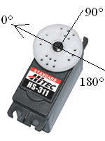 |
t = 1.5 mS T = 20 mS Angle = 90° 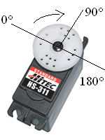 |
t = 2.1 mS T = 20 mS Angle = 180° 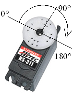 |
Hardware
The hardware design is just the cut out pieces of wood that form the base of the robotic arm & the arm itsself. It also includes the breadboarded circuit that allows the PIC control of the servos. We'll take a 'top down' look at the Wooden Menace.
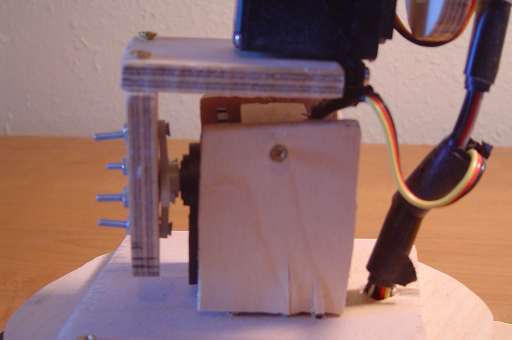
The Grippers
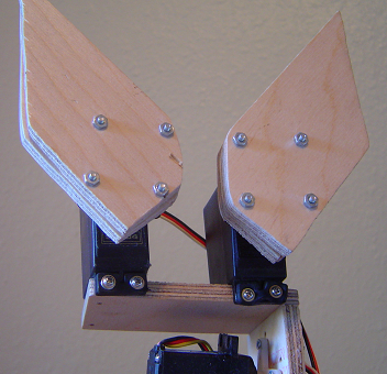
The grippers on the Wooden Menace robotic arm are attached using screws, pieces of wood cut with a jigsaw and small screw & nuts. This simple setup is surprisingly stable. The Hi-Tec 311 standard servos that are used offer enough power to grip a vast amount of objects.
The First Servo Stage
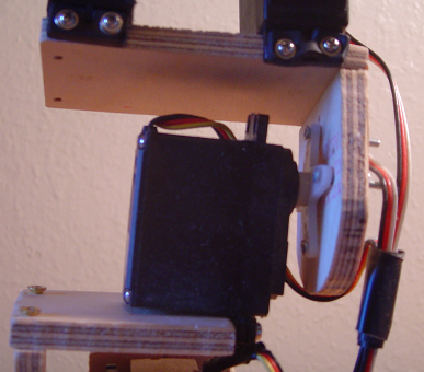
The Second Servo Stage
The last link of the arm has the familiar "L" shape to it and the servo connected to it is also firmly mounted to a circular platform. It is not visible but the circular platform rests on a servo which can rotate the platform & the robotic arm.
The Base
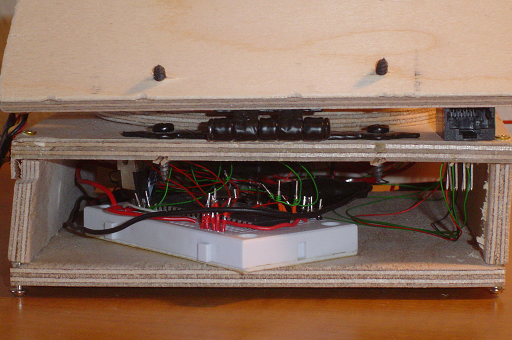
The base of the arm is just a wooden box that houses the electronics that control the robotic arm. On the right you can see the RJ45 female connector & on the left is the breadboard with everything seen on the schematic hooked up. The wiring is a combination or breadboard wire & wirewrap. It would have been a true mess of wire if wirewrap wasn't used, since no large currents were necessary wirewrap was a viable alternative.
Software
Program Download
Main C File
Software Overview
The software for this project is too complex for me to explain well in one sitting. So I'll go over two parts of the code which may not be as easy to understand because of their relationship to the hardware.
Controller Input Polling
The controller used in this project has two HEF4021BT chips inside of it which take input from buttons being pressed. The routine seen in the code is called a 'Bit Banging' procedure. 'Bit Banging' is when you simulate the clock through your own digital device to get the given input. A standard SPI could have been used with much more ease. I didn't figure this out until afterward. Looking at the code, RD1 simulates the clock. RD3 tells the controller to take input of all the buttons at once, then the input taken is clocked out bit by bit into an integer called
/*Begin Controller Data Polling*/

	PORTDbits.RD1 = 1; //Clock Up

	PORTDbits.RD3 = 1; //Take Input

	PORTDbits.RD1 = 0; //Clock Down

	PORTDbits.RD3 = 0;

	/*******************************/

	//Algorithm for capturing input

	for(i=0;i<16;i++)

	{

	PORTDbits.RD1 = 1;

	//Clock Up

	PORTDbits.RD1 = 0;

	//Cloc Down

	c_val += PORTDbits.RD2;

	//Add Input to our integer

	if(i!=15)

	c_val = c_val << 1;

	}

	/**End Controller Data Polling**/
Interrupt Handling
The interrupt handler itsself is too complicated to describe well in this short little html page.
The interrupt controller is set at high priority 0x08. We then define a goto statement in assembly for the function name of the interrupt handler, in our case: InterruptHandlerHigh. Once the interrupt control is correctly implemented interrupts will be sent to the interrupt handler where you can do whatever is necessary depending on the type of interrupt.
//INTERRUPT CONTROL #pragma code InterruptVectorHigh=0x08 //interrupt pointer address void InterruptVectorHigh (void) { _asm //assembly code starts goto InterruptHandlerHigh //interrupt control _endasm //assembly code ends } #pragma code #pragma interrupt InterruptHandlerHigh //end interrupt control
Software: Parting Words
There is much more to the software that I'd love to explain, however it's just not possible in this simple & short write up. I encourage you to look at the actual code available for download as the comments within it should be enough to guide you through the flow of the program.
Data & Observations
Time For a Closer Look
Now that the Wooden Menace is completely built & programmed, it's about time to see if the thing works, and how well it works. The first video is an initial test of the software combined with the hardware, so the electronics are all visible & external. We first test the Wooden Menace's ability to grip objects.
In the second video we'll get a look at the Wooden Meance in its final state of design with all electronics inside as it was meant to be. This video tests the range of movement the robotic arm has.
Conclusion
A Look Back On The Wooden Menace, Robotic Arm
The arm works and I must say the thing is pretty strong. Stronger than you'd think from just watching the videos. The final robotic arm is pretty impressive when you look at the components that were used, however there is definitely room for improvement. Here are a few examples of why this project is good & where it could be improved.
|
|
Movement Improvement
The quick movements seen by the arm are attributed to the incrementor seen in the code & lack of true control software. A revision of the software could improve the movements seen greatly. The wooden design doesn't affect the mechanical movement of the system as much as the software designed to control the servos.
Gripper & Servo Strength
Hobby servos are all capped at certain torques. The Hi-Tec 311 Standard servos that I used for this project is a very low torque servo. There are servos available that offer 100-400% more torque, however they do cost more.
Further Research
In a further project I hope to use all ABS machined steel parts for the robotic arm. This takes away from the truly "homemade" design, look & feel however it results in an all around much better robotic arm.
Conclusion
So the project turned out about as expected. For a first attempt at a cheap, homemade robotic arm I feel the results were spot on. It is able to move objects back and forth (in the video I was throwing PIC microcontrollers into a coffee cup). It also has a wide range of movement and rotation which is what is desired in a robotic arm.