Lukas Fässler
soldernerd.com
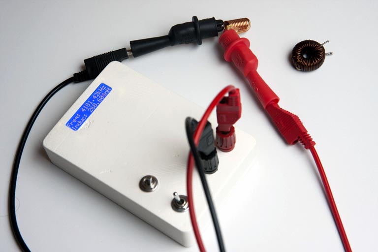
Some of you may have seen my arduino-based inductance meter in the article [1]. The arduino-based meter works well and made a great proof-of-concept. But for everyday use you’re probabely not looking for an arduino solution but rather something that looks and feels more like a multimeter. That’s why I’m following up with this stand-alone version (Figure 1).
 |
||
| Figure 1. | Stand-alone Inductance Meter on PIC16F1936. | |
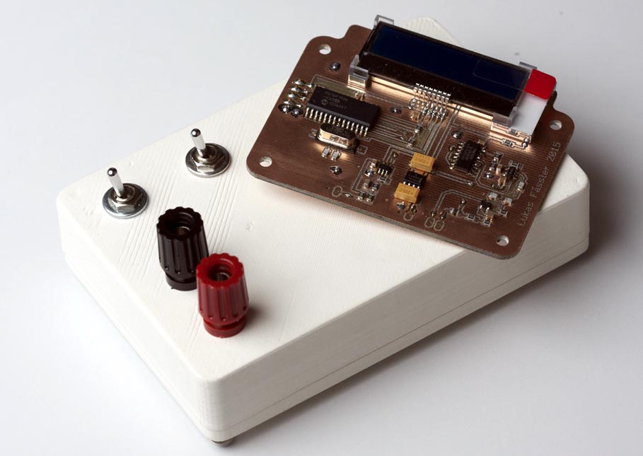
So this version is battery powered and comes complete with a 3D-printed case. It uses a mid-range PIC microcontroller, a Microchip PIC16F1936 (Figure 2). Not that there’s much special about this model, I just happened to have some left from previous projects. I also thought about using a Atmel ATmega328, the same chip that is on the Arduino UNO.
 |
||
| Figure 2. | Stand-alone Inductance Meter on PIC16F1936 Schematic Diagram. | |
Using an entirely different chip means I’ll have to write the software from scratch. But I felt that the Atmega328 was just too much of an overkill just to measure a frequency and control an LCD. They are quite a bit more expensive than the PIC, CHF 3.70 compared to CHF 1.90 @10pieces at Farnell where I get just about all my chips.
Talking of the LCD: The one I’m using here comes with a I2C interface. It’s blue with a white backlight and 2×16 characters and really tiny. I bought 2 of them years ago because they were small and relatively cheap (around 15CHF) and don’t require so many precious I/O pins of your microcontroller. Somehow I never used them but here their small size makes them a good choice. I/O pins aren’t a constraint here obviously as most of the 28 pins are unused.
From a high-level point of view the new software is very similar to the Arduino sketch I wrote for the [1]. If you look a bit closer, you’ll notice some differences for several reasons:
- This project uses an entirely different microcontroller: A PIC16F1936 instead of the Atmel Atmega328
- This code is written in C (for the MikroC for PIC compiler by Mikroelektronika), not Arduino-style C++
- The display I’m using here comes with a I2C interface rather than the familiar Hitachi interface
As expected, the I2C display took me some time to get used to. It’s a Midas MCCOG21605B6W-BNMLWI. It seems to use a Hitachi-compatible controller with a I2C interface built on top of it. I like the concept and will probabely use one of these again. If there is a downside, it’s the data sheet. I had to do quite a bit of guessing and trial-and-error to get it working. I had used Hitachi-compatible Midas displays before so I had some idea what might work otherwise I might have given up. Examples?
- No page numbering. Yes, this is a minor thing but have you ever seen a data sheet without page numbers?
- There is a reset pin. As many reset pins, it’s active-low. But the data sheet never says so. Not explicitly, not with a bar accross the RST, not with a ~RST. Absolutely nothing.
- It explains some of the Hitachi-functionality in great detail but does not really tell you that this functionality is not accessible over the I2C interface.
- Like Hitachi-compatible types, this display needs some start-up time before you configure it. Otherwise it will just not work. But the data sheet doesn’t mention that with a single word.
But it’s all working fine now. The PIC16F1936 has more than enough ROM, RAM and processing power for this meter so don’t expect the code to be optimized in any way. It was just not necessary. It does most of the math in floating-point which bloats the (compiled) code size and is dead-slow on this kind of architecture but it’s still more than fast enough and only uses around half of the available RAM and ROM.
|
||||||
| Figure 3. | Case for Stand-alone Inductance Meter. | |||||
The case was designed using FreeCAD (Figure 3). As the name suggest, it’s a free (and open-source) CAD design tool. This was only the second time I was using it but I found it quite easy to learn.
 |
||
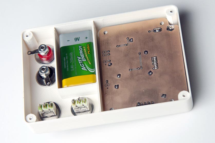
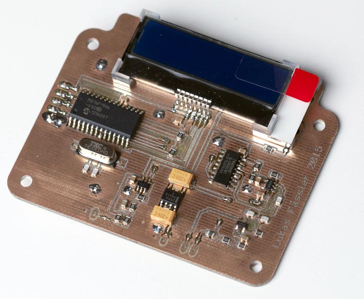
| Figure 4. | PCB for the stand-alone inductance meter with installed components. |
|
PCB for the stand-alone inductance meter was made with a SOIC footprint for the microcontroller (Figure 4).