High-power LEDs challenge electronics engineers to design accurate and efficient, yet simple, driver circuits. Conventionally, driving high-power strings with accurate current requires dedicated switching regulators. Choosing a discrete driver circuit requires an understanding of LED lighting to make the best trade-off. This Design Idea describes a simpler and equally good way to employ the ubiquitous 555 IC.
In the converter circuit in Figure 1, IC1’s pins 2 and 6 connect together, which lets the device retrigger itself on each cycle. Thus, it operates as a free-running oscillator. During each cycle, capacitor C2 charges up through timing resistor R1 and discharges through resistor R2. The capacitor charges up to two-thirds of the power-supply voltage, the upper comparator limit, which 0.693(R1C2) determines, and discharges itself down to one-third the power-supply voltage, the lower comparator limit, which 0.693(R2C2) determines. The total time period, T, is 0.693(R1+R2)C2.
 |
||
| Figure 1. | A free-running 555 timer provides the stimulus for driving a series of LEDs. | |
During the on time, transistor Q1 conducts and stores the energy in inductor L1. When it stops conduction, the stored energy transfers to capacitor C3 through Schottky diode D1.
You can use the following equations to calculate the inductor value. The selection of an inductor depends on input voltage, output voltage, maximum current, switching frequency, and availability of standard inductor values. Once you know the inductance, you can choose the diode and the capacitor.
MOSFET Q1 determines the duty cycle, according to the following equation:

where VINMIN is the minimum input voltage, VOUT is the desired output voltage, and η is the efficiency of the converter, estimated at 80%.
The average inductor current is

where ILAVG is the average inductor current and IO is the output current.
The peak inductor current is

where ILPEAK is the peak inductor current and ΔIL is the change in inductor current.
Assume that the change in inductor current is 25% over the average current. You can compute inductor L1 as

where FOSC is the oscillator frequency. The inductor’s saturation-current rating should be greater than the peak current.
To ensure constant illumination, you must monitor the current through the LED. Resistor R3 senses the output current. Once the voltage drop across this resistor reaches the base-emitter threshold of transistor Q2, it starts conducting, and this conduction reduces the on time of the 555 timer.
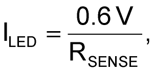
The following equation thus sets the LED current:

where ILED is the LED’s current and RSENSE is the sense resistance.
The minimum and maximum input and output voltages for this circuit are 10.5 and 15 V, respectively. The LED string’s voltage and current are 21 V and 350 mA, respectively. The 6 W LED driver can find numerous applications, including battery-operated portable lighting, solar-operated garden lighting, automotive lighting, bike headlights, and underwater lights. Driving high-power LED strings with standard off-the-shelf components simplifies your design without sacrificing performance.