This is a remake of the fireflies which I did a year ago. I was always fascinated by the emergence of patterns. One I like most is the synchronization of hundreds or thousands of fireflies. First they flash randomly but after some time and influencing each other, they flash in sync.
This circuit simulates fireflies with small microcontrollers. Note that every firefly acts completely autonomously, it is not a preprogrammed pattern. It is a self organizing system.
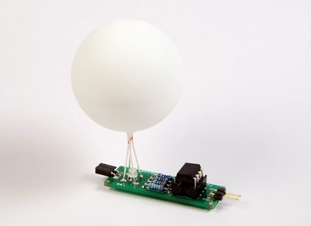
The NG version uses a small PCB (Printed Circuit Board) and a RGB-LED.
Software
Each firefly has a value that stands for the power to flash. This value rises over time. If the power reaches a certain limit, the firefly flashes and the power is reset to zero. If the firefly detects another flash nearby, it increases the power by a small boost value. That way it will flash slightly earlier than last time. Doing so over and over again may lead to all fireflies flashing in sync.
The RGB-firefly uses color to express its mood. If all is in sync, it will flash in relaxed and cool blue. If it detects flashes that are not in sync, it will get a bit uncomfortable and the color will slightly change to green, yellow and red.
The circuit
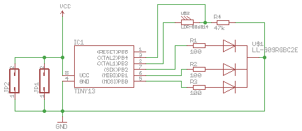
The circuit is rather simple. Main parts are the microcontroller, the light sensor and the RGB-LED. The sensor and R4 are forming a voltage divider. An ADC (Analog Digital Conversion) channel at pin 3 is used to read the values of the sensor. The circuit is designed for 5 V power supply. It has no integrated power regulator.
Parts
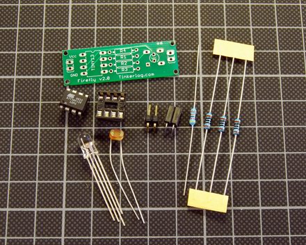
Here are the parts, that are needed for a single firefly.
- Firefly PCB
- ATtiny13v, digi-key
- RGB-LED, 4000 mcd, generic
- 8-pin socket, generic
- 3 * 100R resistor, R1, R2, R3, generic
- 1 * 4.7kR resistor, R4, generic
- Photoresistor (LDR), 4k to 11kR
- pin header and socket (used for power supply)
- ping pong ball
Various types of photoresistors exist. I tried two different versions and both work well. Only resistor R4 has to be adjusted, as R4 and the photoresistor are building a voltage divider. Choose R4 in a way, that gives you a good range of voltage and still limits the current through the photoresistor.
My latest experiments showed that a phototransistor seems even better suited. Compared to the LDR, it does not have a memory effect and reacts faster (~5ms compared to ~50ms). I chose the SFH 3310 and 100k for R4.
One thing to remember while choosing a light sensor, is that the spectral sensitivity of the sensor has to match the humans eye sensitivity (~400 nm - ~700 nm).
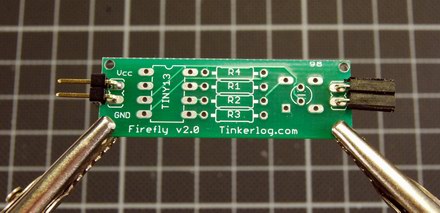
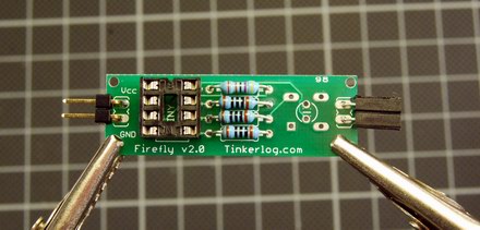
Solder it
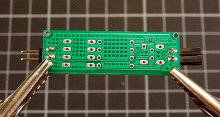
First solder the power connectors. Having a female and male connectors on the boards makes it easy to power a couple in a row.
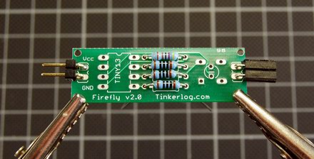
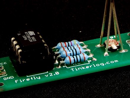
Next insert the resistors. R1-3 are 100R, R4 is 4.7kR (depends on the sensor).
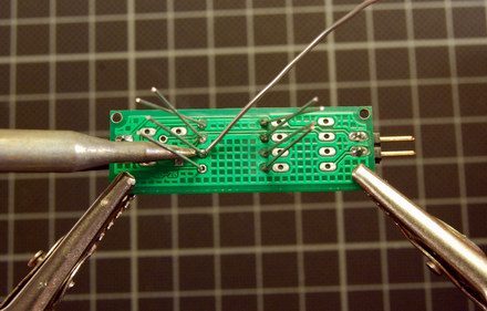
Solder them.
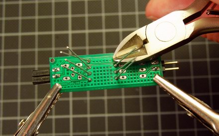
Cut off the legs.
Next insert the 8-pin header for the controller. Note that the notch of the header points up.
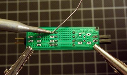
Solder the header.
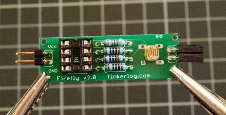
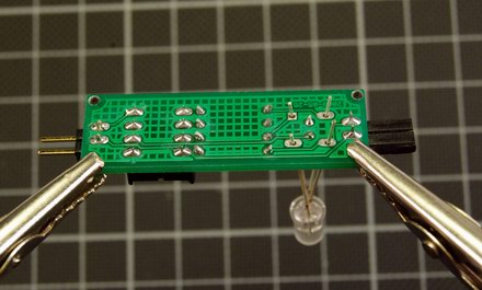
Next insert the LDR. For the LDR the orientation does not matter. For the phototransistor it does! The phototransistor has a long (emitter) and a short leg (collector). Insert it with the long leg at the bottom. And solder it.
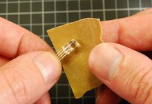
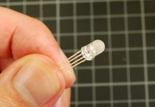
Now prepare the LED. Mine are clear and have a lens on top. Use sandpaper to roughen the surface. That way the light of the LED will be emitted in all directions.
The RGB-LED has four pins. Mine is a common cathode.
- green (short)
- blue (longer)
- GND (longest)
- red (shortest)
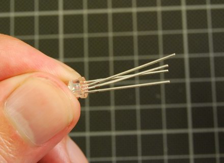
Bend the two inner legs a bit off.
Insert the LED. Be sure to have pin 1 in the hole with the square solder pad. The longest leg is in the diagonal opposite corner. Now solder it.
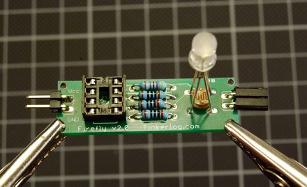
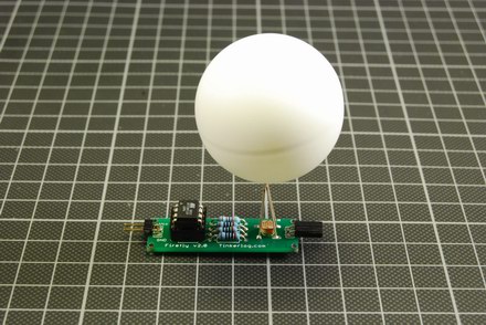
Now it should look like this and we are almost done.
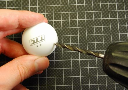
Drill a 4mm hole in the ping pong ball. Use a file to widen the hole a bit. Try to put it on the LED.
Program the controller and insert it into the socket. Take care of the notch.
Here is the final result, the first firefly. Ready for some action.
Issues
There are minor issues that I want to have fixed for the next batch of PCBs.
- I will make the PCB a bit larger to make it more stable.
- The circuit is missing bypass capacitors (100nF and 100uF). It works great without but it’s best practice to have them.
- The sockets for the power supply are not protected against polarity reversal. Not quite sure how to fix this.
Conclusion
Playing with these fireflies is really mesmerizing. It’s not like most computer controlled things because it is non deterministic. Every time you start it, it will produce new patterns and behave differently.
I am quite happy how well the PCB worked out. It was my second design that I have had produced. Now I am feeling confident enough to go for a bigger batch of PCBs.
Downloads and Links
- Buy a kit at the Tinker Store
- Source and schematics (Eagle) rgb_firefly.zip
- Synchronizing Fireflies (first version)
- Synchronizing Fireflies (at Instructables)