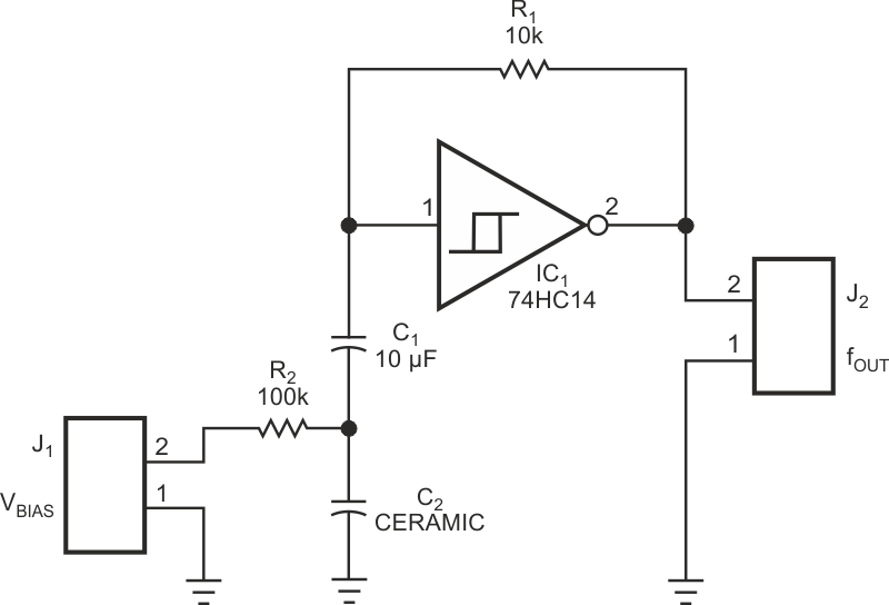
The main purpose for building the circuit in Figure 1 is to study the idiosyncrasies of X5R, Z5U, and Y5V multilayer ceramic capacitors. The circuit is also an inexpensive VCO (voltage-controlled oscillator) with only five components.
 |
||
| Figure 1. | This simple oscillator shows the effect of a dc bias on a multilayer capacitor, C2. |
|
Many types of ceramic capacitors for surface-mount placement are on the market. The parts become continually smaller because of space problems on the board, and the capacitance values continually increase to compete with more expensive tantalum-electrolytic units. Unfortunately, capacitors with X5R, Z5U, or Y5V dielectrics have some undesirable properties. They exhibit voltage-dependent capacitance values. The idea behind the circuit in Figure 1 is to check the influence of a dc bias voltage on the frequency of a simple oscillator. The net result is a low-frequency VCO with a relatively large voltage-gain figure, which depends largely on the type of capacitor you use.
 |
||
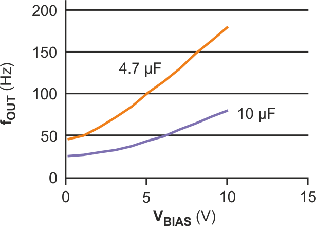
| Figure 2. | The frequency of the oscillator in Figure 1 exhibits almost a 4-to-1 shift for a 4.7-µF Z5U multilayer capacitor. |
|
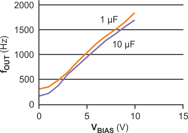
The circuit is a simple oscillator using a Schmitt-trigger inverter. The frequency is a function of R1, C1, and C2. C2 is the ceramic capacitor with voltage-dependent capacitance. Using the value of C1, you can shift the frequency independently of C2. This design uses a stable-foil-type capacitor for C1 to avoid bias-voltage-dependent effects in the measured results. If necessary, you can compensate the temperature coefficient of the capacitor with a combination of NTC, PTC, and metal-film resistors for R1. For measurements, this design uses a simple metal-film resistor. The capacitance change with temperature is normally less than 10% from 10 to 35 °C for Z5U and Y5V and much lower for X5R. Figure 2 shows the measured voltage-versus-frequency graphs with different values and types for C2. For Figure 2, C1 = 10 µF; the orange curve represents a 4.7-µF, 10 V, Z5U multilayer capacitor, and the purple curve represents a 10-µF, 10V, Z5U multilayer capacitor. Figure 3 shows similar plots for values of C1 (orange: 1 µF; purple: 10 µF).
 |
||
| Figure 3. | The value of C1 has little effect on the frequency curves for the circuit in Figure 1. |
|
The moral of the story is: Be wary when using high-capacitance ceramic capacitors with high or variable dc bias; the varying capacitance can greatly influence circuit performance.