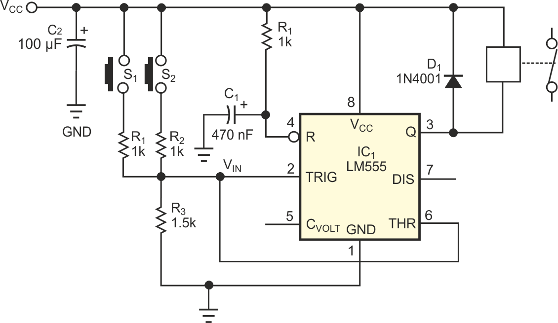
The circuit in Figure 1 provides a safety interlock that checks the actuation of two pushbuttons before enabling a relay. When you push both buttons, the circuit actuates the relay. At that point, you can release one of the switches without the relay's switching off. The circuit was intended to lock out the engine of an underwater propulsion unit. When handling such units on the surface, a person might accidentally press the actuator switch, which is mounted inside the handles of the propulsion unit. ANDing two switches makes the unit safer but requires two hands, a situation that is sometimes unsuitable. Using the circuit in Figure 1, you need two hands to start the engine; once the engine is running, one hand is sufficient to keep it running. When you press no switch, the engine shuts off. The circuit uses a simple 555 timer, IC1 in a unique way. In this circuit, the 555 serves as a window comparator, followed by a memory element.
 |
||
| Figure 1. | Two buttons turn on the relay; one buttons keeps it going. | |
Actuating one pushbutton puts the input voltage between the two levels of the comparator and thus has no effect on the state of the 555's internal flip-flop. Only when you press two buttons does the voltage go above the high trigger level and set the flip-flop in the 555. Releasing one button brings the voltage back to a level inside the window and has no effect on the state of the flip-flop. Releasing both buttons brings the input level to ground, thus below the low trigger level, and resets the output. Because the 555 derives its internal levels from a resistive divider, the supply voltage has no influence on the behavior of the circuit. The reset input of the 555 connects to an RC circuit, so the IC resets the output upon power-on. By playing with the resistor values, you can obtain many operating conditions. The high output drive of the 555 can actuate almost any type of relay. The diode at the output protects the 555 from the back-EMF of the relay coil when the relay shuts off.
The detection levels of the 555 are one-third and two-thirds of the supply voltage. R1 and R2 are of equal value. When you push no button, the input connects to ground via R3. When you push one button, the input voltage rises to
VCCR3/(R1+R3).
When you push both buttons, the input voltage rises to
VCCR3/(0.5R1+R3).
If R3=1.5 kΩ, and R1=R2=1 kΩ, you have the following conditions:
No buttons: VIN=0 V; thus, the output is off.
One button: VIN=0.6VCC – below the 0.66VCC high level; thus, no change is in state.
Two buttons: VIN=0.75VCC – above the 0.66VCC high level; the relay switches on.
The circuit lends itself to modifications. You could add an emergency cutoff by connecting a switch across C1, providing a permanent reset of the output. Or, for delayed action, you could connect capacitors across R1 and R2. You can also manipulate the detection levels by connecting a resistor between Pin 5 and VCC or ground.