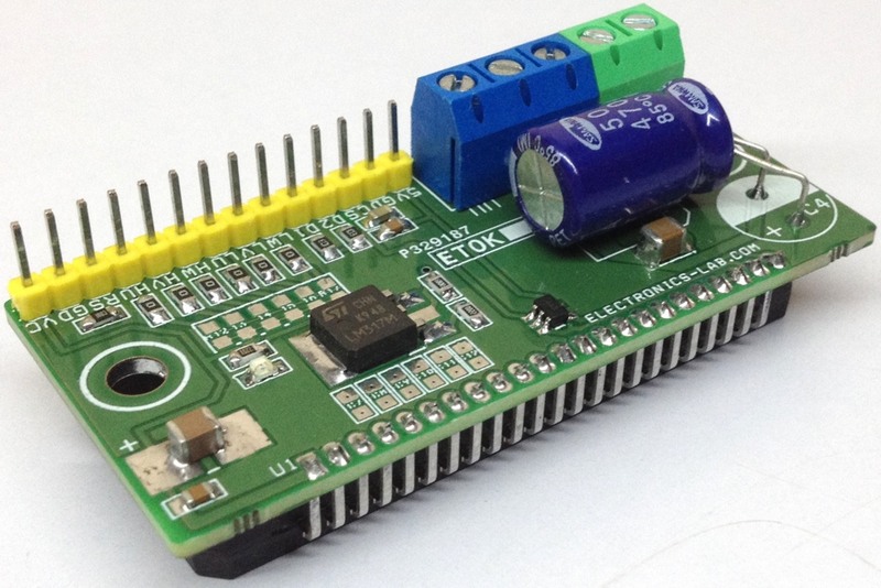
This project is based on STK984-090A from ON Semiconductor which is a fully-integrated inverter with current rating 20 A and supply voltage 40 V DC (Figure 1). It has been designed to drive the Brushless DC Motors (BLDC) and permanent magnet synchronous motors (PMSM), the module works as output driver which include power stage and current sense circuitry, header connector provided to interface with Arduino or other micro-controller for PWM inputs and current feedback. Screw terminals help to connect the motor and power supply.
 |
|
| Figure 1. | 20A/40V Integrated Power Module for DC Brushless Motors (BLDC). |
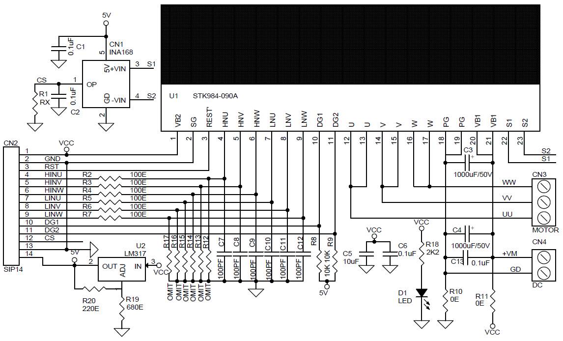
INA168 IC is a current sensor and measures the current across the internal sense resistor and provides an output voltage. This voltage can be feed to Arduino analog pins to detect the current flowing across the MOSFET’s. LM317 voltage regulator provides 5 V DC to power the current sense IC INA168 and other logic circuitry (Figure 2). D1 motor power LED. Maximum PWM frequency 20 kHz and duty cycle 10 to 90 % or 100%.
 |
|
| Figure 2. | Schematiс Diagram for 20A/40V Integrated Power Module for DC Brushless Motors (BLDC) . |
The project is a fully-integrated inverter power stage consisting of the gate driver, 6 Mosfets and high side current shunt resistor, suitable for driving permanent magnet synchronous motors and brushless DC (BLDC) motors. The MOSFETs are configured in a 3-phase bridge with a single drain connection for the lower legs. The power stage has a full range of protections including cross conduction protection, external shutdown and under-voltage lockout. Built-in charge pump for operation with low battery voltage, over current protection on both high side and low side Mosfets, over-temperature shutdown, under-voltage and over voltage shutdown for defined operation at all input voltages, integrated high side resistor for external current sensing.
Current Feedback Output
The device INA168 converts a differential input voltage to a current output. This current is converted back to a voltage with an external load resistor that sets any gain from 1 to over 100.
Current feedback Output voltage can be set using this formula:
V = Current × 3 mohms × R1/5 Kohms (Is.Rs.RL/5 Kohms)
Note : 3mOhms Internal Shunt Resistor of STK984-090A
Output Voltage Range
The output of the INA168 device is a current that is converted to a voltage by the load resistor, R1, RX. The output current remains accurate within the compliance voltage range of the output circuitry. The shunt voltage and the input common-mode and power-supply voltages limit the maximum possible output swing. The maximum output voltage (Vout max) compliance is limited by either Equation:
Vout max = VIN– – 0.5 V
Note: Refer to STK984-090A datasheet for more information, C7-C12 capacitors are optional used as RC filters and recommended in a noisy environment. Required large size heat sink for peak load.
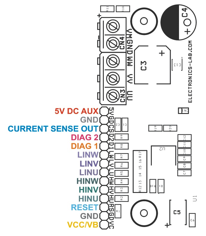
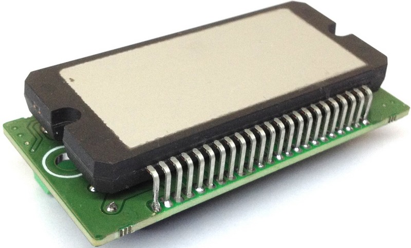
Parts Lists is listed in Table 1. Module connections and components placement shown in Figure 3. The view of the printed circuit board from the driver installation side is shown in Figure 4.
| Table 1. Part List | |||||||||||||||||||||||||||||||||||||||||||||||||||||||||||||||
|
 |
|
| Figure 3. | Component placement and connections for 20A/40V Integrated Power Module. |
 |
|
| Figure 4. | The view of the PCB from the integrated driver installation side. |