A solar day lamp is a simple, inexpensive device for bringing “daylight” to dark interior spaces whenever the sun is shining. This article provides complete instructions for designing lamps using both passive and active current limiting circuits. It also demonstrates how using a simple active current limiting circuit can provide significant improvements in efficiency, flexibility, and longevity of the LEDs.
As the name suggests, a solar day lamp only provides light during the daylight hours. Since it has no energy storage, it is very simple to make, cost effective, long-lived, and requires little or no maintenance. While the concept may appear odd at first, they hold great promise as a low-cost solution for brightening dark interior spaces. The lamp designs we will explore in this article are all intended for off-grid operation, where they deliver free light from sunrise to sunset.
Since a day lamp does not have a battery, none of the power from its solar array is consumed by the losses of charge and discharge cycles, which allows all the power generated by the solar panel to be turned into light. Additional efficiencies may be achieved if the lamp’s simple resistive current limiting circuit is changed to a slightly more complex active current limiting circuit, as we will see in the second half of this article. We will compare the performance and efficiency of two different solar day lamp designs under changing sunlight conditions to see if active current limiting provides any substantial advantages.
A solar day lamp’s LEDs must be protected against over-current conditions that can damage their junction structure, causing reduced output, or even failure. The simplest method of current limiting is to place a resistance in series with an array of LEDs. Typical specifications of a 12 V 10 W solar photovoltaic (PV) panel are as follows:
- Voltage at maximum power VMP = 17.4 V
- Current at maximum power IMP = 0.58 A
These values correspond to a standard test condition of 1000 W/m2 of solar illumination. If the illumination reduces, the magnitude of VMP also reduces. For design purposes we will use the values of VMP and IMP given in the specifications.
Resistor current limiter
LED lamps are easily available in the market. A typical lamp consists of a pre-assembled array of white LEDs mounted on a metal clad PCB. Usually their LEDs are rated for 1 W power (two 0.5 W LEDs in parallel). The forward voltage (VF) of these LEDs is typically around 3 V.
For our application, we derive the following:
Number of LEDs is
Rounding down gives us the maximum number of LEDs we can use in series = 5 LEDs
Residual voltage equals

Maximum current in the LED string is
where PLED is LED power.
To ensure the longest life for the LEDs, it’s necessary to run them below their maximum rated current. In addition, limiting the brightness of the individual LEDs keeps them from becoming unpleasant to the eyes. Hence, we will limit the LED current to about 200 mA.
Resistor selection
Since the solar day lamp requires long wires between the rooftop solar array and the interior of the building, wire resistance must be factored into our design. For this exercise, we have selected 10 meters of good quality wire, which offers about 0.8 ohm total resistance.
Drop across resistance is equal to

where VDR is wire voltage drop.
Value of current limiting resistance
where VR is voltage drop across resistance.
The circuit diagram of the resistor-based day lamp is shown in Figure 1.
 |
||
| Figure 1. | This schematic of the 10 W solar day lamp includes resistive current limiting. | |
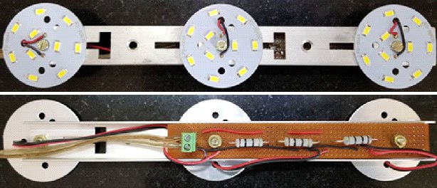
Figure 1 illustrates three LED arrays, A, B, and C, each having 5 LEDs (L1-L5, L6-L10, L11-L15) and a 10 Ω current limiting resistor. The three PCBs containing the LED arrays were assembled on an aluminum channel, which acts as a mechanical support and as a heat sink (Figure 2). To optimize heat transfer, a thin layer of thermal compound was applied to the LED PCBs before they were mounted onto the aluminum channel.
 |
||
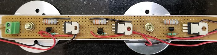
| Figure 2. | This photograph shows the top and bottom sides of the solar day lamp with 3 LED arrays. | |
Disadvantages of resistor current limiter
Under conditions when the PV panel is exposed to illumination levels above the standard value, its output voltage is greater than our calculated value for VMP, causing the lamp’s LED current ILED to rise above the maximum calculated value. The resulting over-current conditions have the potential to reduce the LEDs’ output, service life, or both.
Another problem arises if the over-current condition causes one of the LED arrays to fail. In this case, the reduced load on the solar panel causes its voltage to rise further and damage the remaining arrays. A similar condition can happen during testing unless all three LED arrays are connected to the panel. With this in mind, do not test a single LED array. Another problem arises if we use a higher-power PV panel to drive several lamps. In this configuration, we cannot use switches to turn OFF individual lamps because the resulting rise in supply voltage will damage the remaining lamps.
 |
||
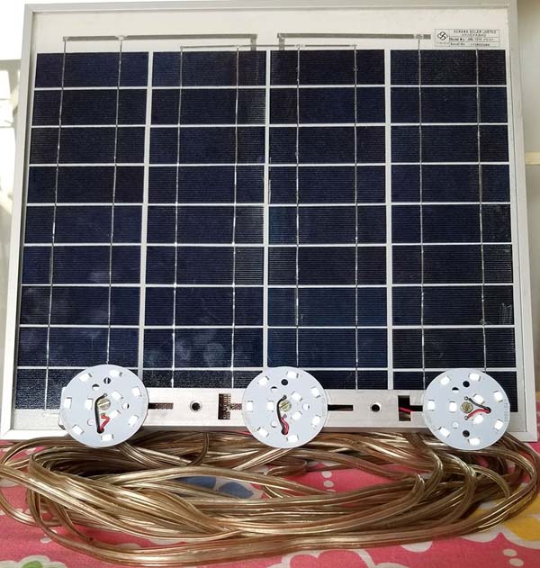
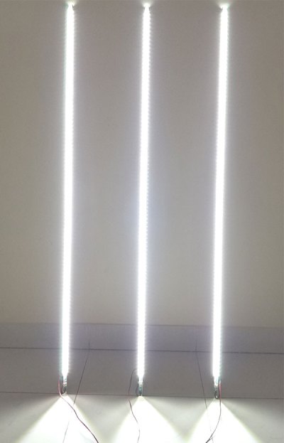
| Figure 3. | This 10 W solar day lamp is ready for use. | |
Clearly, a different approach is desirable for most applications. Figure 3 shows the completed solar day lamp.
Design #2: Active current limiter
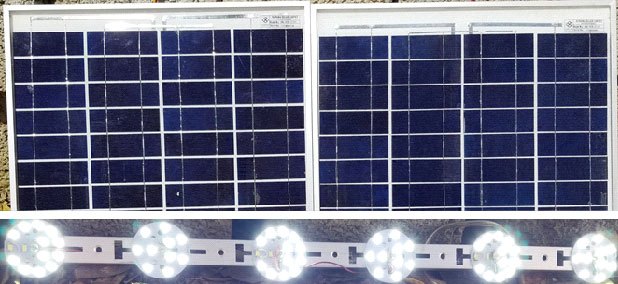
The resistors in the circuit of Figure 1 can be replaced with an active current limiting circuit. In this design, we are using two 12 V PV panels connected in series to drive longer strings of LEDs to provide more light. Note that if it’s more cost-effective, a single 24 V PV panel may be used instead of the two 12 V panels.
The values for this design are calculated as follows:
Number of LEDs per series string is
Rounding down, the maximum number of LED in a series = 11 LEDs.
Number of LED arrays is
(round up to 3 arrays).
Current through each array
 |
||
| Figure 4. | Here is the schematic of a 20 W solar day lamp with active current limiting. | |
As shown in Figure 4, the current limiting circuit consists of a power transistor Q1 (TIP31C). The LED array A is connected to the collector of Q1. Q1 is biased using resistor R1. In the emitter circuit, current sensing resistor R2 is included. Voltage across R2 is sensed using Q2. When the drop across R2 reaches 0.6 V, Q2 turns ON. This pulls down the base voltage of Q1, and current is limited to:
 |
||
| Figure 5. | This is the LED array for a 20 W day lamp. | |
Figure 5 shows the construction of 20 W day lamp. To get 11 LEDs in each array, we are using two LED PCBs in series. The first PCB has 5 LEDs, and is rated at 5 W. The second PCB is a 7 LED array, rated at 7 W.
 |
||
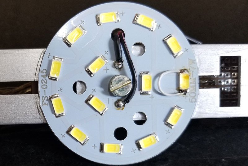
| Figure 6. | One of the LEDs has been deliberately shorted to reduce the array to 11 LEDs. | |
When connected in series, the two PCBs become a 12 LED array that can be shortened to the 11-LED length we need. The photo in Figure 6 shows how one of the LEDs was deliberately shorted to reduce the array length to 11 LEDs in series.
 |
||
| Figure 7. | This close-up of the PCB shows the lamp’s three current limiter circuits. | |
 |
||
| Figure 8. | This 20 W solar day lamp with active current limiting is ready for use. | |
The advantages of active current limiting
The active current limiting circuit maintains the LED current at a constant, safe level during periods when higher-than-average solar inputs cause the panels to generate voltages > VMP. In addition, even if one LED array fails, the remaining arrays will continue to work without any problem. It also allows the higher-power 20 W PV panels to support several LED lamps that can be switched on or off as needed. Despite the varying load, the current limiter circuit ensures that each panel’s LED current does not exceed its set value.
Higher-power designs
In contrast with the earlier single panel design, which uses resistive current limiting, the actively-limited two-panel system is able to drive one extra LED per array, thereby producing more light. As the following calculations show, this advantage can be applied to larger lighting systems:
For 3 PV panels in series number of LEDs is
Rounding down, the maximum number of LEDs in series = 17 (two extra LEDs)
For 4 PV panels in series number of LEDs is
Rounding down, the maximum number of LEDs in series = 23 (three extra LEDs).
Design details of a 23 LED array:
- Number of PV 10 W panels: 4
- Number of arrays with 23 LEDs each: 3
- VMP = 69.6
- Residual voltage
- Drop across resistance

- Current limiting resistance
Note: In this design we have to use a thicker wire in order to reduce drop.
Thus, we see that with each additional panel that is wired in series to the system, the lamp array is able to drive an additional LED.
Performance evaluation
Performance of the solar day lamp is evaluated based on how well it tracks the panel’s maximum power point (MPP) curve under different values of solar illumination. For a given PV panel, there is a MPP curve. This curve is generated by connecting variable load resistance to the panel. The load resistance is varied to get the MPP (VMP and IMP) for a given solar illumination. This process is repeated for different conditions of solar illumination and the data is used to plot a graph of VMP vs power.
While testing the day lamp, lamp current and PV voltages are recorded for a series of different conditions of solar illuminations. Tests were carried out on the following lamp versions and the results are compared with the standard MPP curve.
 |
||
| Figure 9. | This graph compares the power output of a lamp with 5 LED arrays and the MPP curve. |
|
|
||
| Figure 10. | Compare the power output of a lamp with 11 LED arrays to the MPP curve. |
|
 |
||
| Figure 11. | Compare the power output of a lamp with 12 LED arrays to the MPP curve |
|
 |
||
| Figure 12. | Compare the power output of a lamp with 23 LED arrays to the MPP curve. |
|
Figure 9 shows the results for a single PV panel having 5 LEDs in each array and resistor current limiter. Figure 10 represents two PV panels having 11 LEDs in each array and active current limiter. Figure 11 shows the results for two PV panels having 12 LEDs in each array and active current limiter. And Figure 12 shows four PV panels having 23 LEDs in each array and resistor current limiter.
 |
||
| Figure 13. | This photo shows the design with 4 PV panels and 3 arrays with 23 LEDs each. |
|
In conclusion, the lamp using a resistive current limiter circuit tracks the MPP curve well at low power levels. At higher power levels the lamp provides significantly less power. The solar day lamp using active current limiting closely tracks the MPP curve, thus providing maximum light for any given power input. In this configuration, the optimum number of LEDs in an array is 11 as seen in Figure 10. Figure 11 shows how the power output of a 12-LED array is significantly lower.
In some regions of the above plots, it is seen that the power output is even higher than the MPP curve. This may happen due to one or more of following reasons:
- The values of VMP and IMP are not fixed. Manufacturers specify a typical tolerance of about ±5%.
- The MPP curve is generated using resistive load. In contrast, LEDs are nonlinear loads and the panel may work differently with non-linear loads.
The reason why LED loads track the power so well is because of the variation in LED forward voltage VF with current. As the LED current reduces, there is a slight reduction in VF. This matches with the MPP curve, which results in close tracking naturally.
Solar day lamps offer the simplicity, low cost, and longer life that make them ideal for many residential, commercial, and industrial applications. They can also bring much-needed affordable light to low-income families and rural communities where reliable electricity is not available. A dedicated IC that provides simple active current limiter circuits could further simplify construction and reduce cost.