When you need a precision peak detector, you would usually implement it with one or several op amps and a few other associated components. This technique usually works well unless your design requires operation higher than a few kilohertz. In designs requiring such operation, the accuracy of the circuit severely deteriorates unless at least one of the amplifiers has a high slew rate and frequency response extending to tens or even hundreds of megahertz. Performance depends on the desired frequency response and peak-to-peak input-voltage range of the peak detector (Reference 1). The circuit in Figure 1 uses a moderately fast, inexpensive comparator instead of a high-slew-rate op amp to implement the peak detector. This circuit provides wide bandwidth and high accuracy without the use of precision components, and it's simple and inexpensive—about $3.50 (1000).

The high-input-impedance FET source follower, Q1, and the associated circuitry enclosed by the dotted line in Figure 1 buffer the input to the comparator. This buffer is essentially the design published in Reference 2. Op amp IC2D forces the dc voltage at the input to the comparator at the junction of D1 and R3 to be equal within a few millivolts to the dc voltage at the FET gate. If the peak detector has a driver with an impedance of less than approximately 150Ω, you can eliminate the buffer in the dotted-line box. However, as the source impedance increases, the accuracy of the peak detector decreases if you don't use the buffer. An LM306 comparator, IC1, provides sufficient speed and current to charge the holding capacitor, C3, over an input range of 25 Hz to more than 1 MHz, with an input-voltage range of 500 mV peak to more than 4V peak. The comparator exhibits a few millivolts of hysteresis, which improves its switching speed and prevents random oscillation when its input voltage is in its linear range.
This circuit works by essentially creating its own reference for the negative input of the comparator. If the voltage on the positive input of the comparator is greater than the voltage at the negative input, the comparator's output goes high and charges capacitor C3 until the voltage on the capacitor is a few millivolts greater than the voltage on the positive input. Then, the comparator stops charging C3 until the cycle repeats. This action ensures that the voltage on holding capacitor C3 is nearly equal to the peak voltage at the input to the comparator. Schottky diodes D2 and D3 couple the output to the holding capacitor, C3. The feedback from the output of IC2A to the junction of D2 and D3 keeps D3 biased to 0V when it is off, thereby preventing reverse leakage through D3 (Reference 2). The feedback also provides reverse bias to D2 when the output of the comparator is pulled low. The IC2A FET-input op amp has low input-bias current, so it does not discharge C3 between charging pulses. IC2C buffers the negative input of the comparator for the same reason. The 10-MΩ resistor, R11, provides sufficient discharging of C3 so that the dc output from IC2B decay to a negligible level in two to three seconds after removal of the ac-input signal.
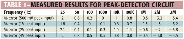
R13 and C6 filter the dc output to remove most of the noise that the comparator causes. R14 provides a small amount of attenuation of the dc output, so that R15 can provide approximately ±2% adjustment of the dc output. For best precision, set R15 for minimum gain and apply a 500-mV, 10-kHz signal to the input. Adjust R9 for 500-mV dc output. Then, apply a 4V, 10-kHz signal and adjust R15 for 4.010V-dc output. Check and repeat these two adjustments if necessary. If a precision ac source is not available, you can use an accurate dc source and a high-impedance voltmeter for calibrating the circuit. Apply 500-mV dc to the input and adjust R9 for 499 mV at Pin 10 of IC2. Then, apply 4V dc to the input and adjust R15 for 3.980V output (Pin 8 of IC2). The maximum peak input voltage is approximately 5V, because the maximum input-voltage specification for the LM306 is ±7V. The accuracy of the circuit decreases when the input peak is higher than 4V. Remember to use a blocking capacitor in series with the input if the signal to be measured includes a dc offset that can cause the peak input voltage to exceed approximately 5V. Table 1 shows measured results for the circuit. If desired, you can delete R9, R10, R14, R15, and R16 from the circuit and still obtain good performance.
References
1. "Fast amplifiers simplify ac measurement," EDN, May 9, 1996, pg 100.
2. Williams, Jim, A Designer's Guide to Innovative Linear Circuits, Volume II, Cahners Publishing, 1987.
3. Graeme Jerald, "Peak detector advances increase measurement accuracy, bandwidth," EDN, Sept 5, 1974, pg 73.