David W. Bray
This article describes details for constructing a 1-Wire Barometer which will work on a Dallas Semiconductor Corporation 1-Wire network. It differs from the popular Version 1.1a in that it has more than twice the resolution.
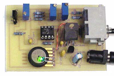
As with 1-Wire Barometer Version 1.1a, this design uses a Motorola MPX4115 Silicon Pressure Sensor, a Dallas Semiconductor DS2438 Smart Battery Monitor (to perform 1-Wire analog to digital conversion), an operational amplifier, two voltage regulators, two diodes, a LED, and several resistors and capacitors.
For background information please see the Version 1.1a web page.
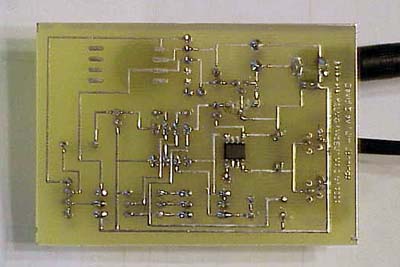
Printed Circuit Board
Jim Jennings has designed a single sided printed circuit board for this barometer, as he did previously for Version 1.1a. You can either make the PC board yourself or purchase it from Far Circuits. This new V2.0 board is universal in that it may be used to build either barometer V1.1a or V2.0.
Circuit Details
The circuit requires an additional power source other than that of the 1-Wire network. The MPX4115 requires about 7 ma of current. This is more than a 1-Wire network can provide without an elaborate circuit to store parasitic power from the 1-Wire network for short burst of current for pressure measurements.
The resolution of the barometric pressure is about 0.00417 inHg (0.0139 kPa) for a pressure range of 31.0 to 28.0 inHg (105.0 to 95.0 kPa, or 1050 to 950 mb). Better resolutions are possible with a more restricted pressure range.
Circuit Schematic
This schematic is missing the modulator connector. See downloads below.
Circuit Description
For barometric pressures the MPX4115 output voltage ranges from about 4.25 to 3.79 volts at sea level, and about 2.77 to 2.45 volts at 10,000 feet. Most of this range is above the active voltage range of a 5 volt opamp circuit. In effect the sensor voltage is referenced to the power supply, not ground as desired. Fortunately the DS2438 Smart Battery Monitor accepts inputs as high as 10 volts. Thus by powering an opamp from 10 volts the output of the MPX4115 is well in the opamp and DS2438 range.
The MPX4115 output is fed through a RC filter to opamp stage, U1B, which has a fixed gain of approximately 4. This stage has an adjustable voltage input which is added to the barometric sensor output within the opamp, thereby allowing the adjustment of the output voltage offset to the A/D converter.
This in turn is fed to opamp stage, U1A with an adjustable gain. It is capable of a gain range of 1/1 to about 4.14/1.
The two 10-turn potentiometers (pots) control the gain and offset. R3 controls the gain of U1A and R4 controls the offset of the output voltage to the 1-Wire DS2438 A/D converter.
Note that the MPX4115 feeds R1 through a jumper. This allows easy change of the input voltage from a source than the MPX4115 for calibration.
To be continued