Video surveillance systems have rapidly grown from being a specialized equipment for high-risk areas (like banks and airports), to the point of being standard facilities of most places open to the public. Nowadays, no shopping centre, office, industry can afford lacking one. In conjunction with a time-lapse video recorder, these little cameras play an active role discouraging theft and collecting evidences and precious information about the offenders.
Despite their huge commercial success, video surveillance recorders have had little impact on residential markets. No doubt they would be useful at home as well as they are at work: according to the Police, most home thieves go unpunished, so in a sense homeowners must help for themselves.
I have always wanted a video recording system protecting my house, but commercially available systems didn’t persuade me. Let’s see why.
Standard systems won’t do.
Commercially available systems are not designed for home use, and unfortunately don’t adapt well to the new role. The problems start with the time-lapse recorder, which is a special recorder capable of recording several days of slow-frame-rate video on an ordinary VHS tape or a big hard disk. This is an expensive piece of equipment: prices start at $300 for a tape recorder, but if you look for a reliable brand-name device be prepared to pay more than $1000, and $1500 for a hard disk system. Most units are solidly built and usually they worth their money, nonetheless my concept of reliability for home use is “install and forget”, which doesn’t match hard disks or tape heads spinning forever.
If the price tag and periodic functionality inspections are OK for you, there is always the problem of placement. You need a out-of-sight place, spacious enough to accommodate the recorder and the video display ($150), because images can only be inspected using the original recorder.
Another issue differentiating between commercial and residential systems is the way you run the wires from the camera to the recorder. For shops and offices you can easily pass the cable under the floor or over the ceiling, but if you live in a old brick house like me, you simply can’t do it without cutting the walls - another $2000 to the bill. You can try RF-linked cameras, if you don’t care wiping out all WiFi networks in your neighbourhood (and you are not concerned about exposing your privacy). Alternatively, you can use good WiFi cameras that by definition preserve the network, with only drawback of consuming most of the bandwidth for themselves…
My tailored solution.
The Witness Camera is a combination of a VGA CMOS camera, a passive-infrared movement sensor, a 1 GB SD-card (or bigger), and an AVR Mega32 microcontroller implementing a solid-state time-lapse recorder. It is a compact, complete, self-contained surveillance system designed with home users in mind. It can be installed in minutes wherever there is a mains plug, and it is affordable because of it is built using an handful of inexpensive parts.
For most typical domestic environments, it can store more than one month of images at a maximum rate of a colour picture every 2 seconds (320×200 pixels, comparable to VHS-CCTV recorders), or 3 seconds (VGA, 640×480 pixels). Recording starts automatically upon detecting a movement. Alternatively you can set a timer, or supply an external trigger, and even do continuous recording.
You only need to setup the camera once. An infrared remote control and voice-prompt menus allow easy operation, even when the camera is concealed or installed in places like ceiling corners.
When the card is full, new images replace automatically older ones, so you get always the most recent snapshots. You won’t even notice the system is working; there are no moving parts, no fans, no electrical power wasted.
In the (unfortunate) case you need to investigate the images, just take off the card from the camera and put it on any PC or laptop with an SD-card slot. Specialized software is not required: the Witnesscam records its files using a standard file system (FAT16 or FAT32) and image compression format (JPEG). Retrieval is immediate as the camera sorts the pictures in folders according by date and time.
How it works.
The Witness Camera operation is conceptually simple, but involves many ingredients. Some are physical components, the others are software blocks. To make things clear, I will introduce them gradually, according to the operating mode.
The most important hardware component is the ITC328 camera module. It consists of a VGA (640x480) CMOS colour sensor and a JPEG-compression chip. The compression engine includes a serial interface at 3.3V levels that can be connected directly to a microcontroller’s UART. Issuing the appropriate commands you can take snapshots as JPEG-compressed byte streams. The camera comes in a handy module with everything including the lens, and a 4-pole connector for power and data.
The most important software component is the AVR-DOS file system. It is a library for driving mass storage devices, like SD and MMC cards, CompactFlash, and even hard disks connected to the AVR microcontroller. It provides an high-level programming interface for accessing disks formatted according to FAT16 or FAT32 specifications, which means its files are directly compatible with PCs. By linking AVR-DOS to your program you can create and open files, write and read data, create and change directories with simple commands, like you would do on a PC. Restricting read/write access to one file at a time, the FLASH and RAM footprints are minimal (8kB and 1.3kB), making it possible to use a small 8-bit AVR device like the Mega32 for tasks usually accomplished by 16- or even 32-bit processors.
These two blocks are the foundation and starting point of the Witness Camera design. With the aid of the simplified block diagram of Figure 1, let’s see how these block interoperate during normal operation as a time-lapse recorder.
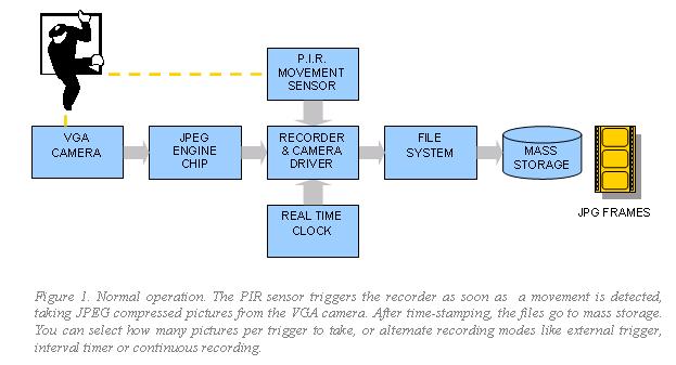
This diagram introduces a second hardware block, the PIR (Passive Infra-Red) movement sensor model ITM256. This module can sense people up to 5 meters/16 feet away, by measuring changes in the infrared radiation caused by human body temperature. It is a cheap mass-production part from the burglar alarm market, including a Nicera RE200B thermopile and a KC778B companion chip in dice form, under the familiar epoxy blob. A Fresnel lens with an angle of 60º snaps in the PCB, which connects to the outside world by means of a short 3-pole cable (power, ground and signal).
The PIR triggers a software block, the recorder, which is in charge of deciding if and how many pictures to take according to its trigger inputs and operating mode. The recorder controls the camera driver (another software module) in order to get the JPEG byte stream. The real-time clock is an hardware feature of the AVR controller, and the recorder uses it both for time-stamping the JPEG files with current date and time, and as an interval timer if time-lapse photography mode is selected. After time-stamping, the recorder hands over picture data to the file system, which stores it permanently on the SD-card.
Having a file system in place opens up many possibilities to the world 8-bit microcontrollers. Once you try it, it’s hard to go back. The capability of accessing huge data files is exploited also in the other operating mode of the Witnesscam, the setup mode, which is outlined in Figure 2.
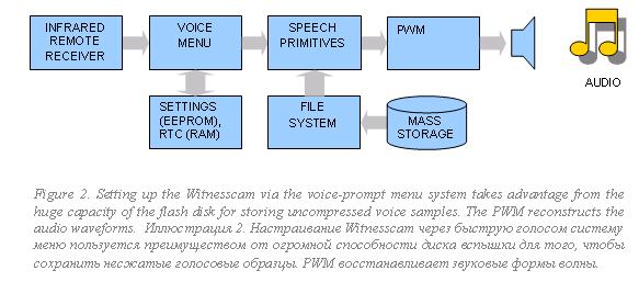
During setup the user interacts by means of an infrared remote control (I have used an off-the-shelf universal remote), and the Witnesscam responds with voice prompts. The prompts guide the user through the editing of all the operating parameters (date, time, recording mode, picture resolution, number of frames to take each time the sensor triggers…).
The voice menu block is the software module running the user interface. It takes the pulse train from the infrared receiver as input, and after decoding it uses it to edit the settings from AVR’s non volatile memory. During this process, it invokes the speech synthesizer module, which provides the primitives needed to compose and play the messages.
The speech synthesizer takes advantage from the existing mass storage capabilities, using the file system in read mode. The flash disk must be prepared in advance with a special set of files with audio samples for each word or status messages to be pronounced, e.g. the file “15.PCM” stores the waveform samples for the word “fifteen”. Reconstructing the audio signal is then a matter of opening the file and sending the samples to the AVR PWM feature.
Samples compression is unnecessary. Years ago, devoting more than one megabyte of flash for this purpose would have been regarded as extravagant opulence, but today this figure represents about 0.1% of flash disk capacity! So this technique is cheaper than an LCD display, and ways more effective, because it’s expected that the camera is concealed or placed out-of-the-way.
The complete picture.
The complete block diagram of Figure 3 is the sum of the two previous diagrams plus some extra details. The software modules are draw inside the AVR Mega32 body. For ease of reference, the respective source file names are given in italics.
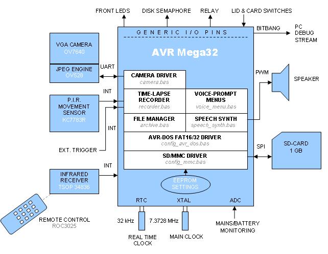
This chart shows the file system exploded into its constituents: the AVR-DOS library, the underlying SD-MMC software driver which takes care of low-level access to the physical media, and the SD-card itself. The card talks to the AVR via the hardware SPI interface, which is notably fast in Mega devices.
There is a new file manager layer (file archive.bas) mediating between the recorder and the AVR-DOS file system. Its purpose is to provide helper functions like determining the oldest files in the archive, deleting unused stuff to make room for new images, and creating an orderly set of directories and files to archive the pictures according to the time stamp.
Another added functionality, introduced in order to preserve disk integrity, is power monitoring. The system must cease any disk write in case of problems. It measures both main and battery voltages using the 10-bit AD converter of the AVR.
The remaining functions are not essential for the Witnesscam to work, but make development and use much easier. With the PC debug port you can log system operations messages (disk size and free space, JPG file size, read and write file access details, remote control codes received) for diagnostic purposes – or just for the pleasure of watching the internal clockwork in action.. I created the port bit-banging an I/O pin, a technique that works perfectly for low baud rates (9600) and allows setting of signal polarity. That is, you can connect the AVR pin straight to the RX pin on PC serial port, without any interface logic (a priceless trick for debug).
The AVR can drive LEDs from all of its general purpose I/O pins. I have provided two status indicators on the front panel. They are useful to verify the PIR sensor range and to check if disk is actually recording.
Notably, I have introduced two extra LEDs inside the box, next to the SD-card slot. I call this the “disk semaphore”: when the green light is on, it’s safe to extract or insert the SD-card from its slot. A red light signals that a disk operation is in progress, and you must wait before touching the SD-card. A simple algorithm inside the main recording loop determines what light to put on based on the status of the recorder, the card detect switch from the SD-card receptacle, and the lid detector switch that notifies the system when the camera case is opened.
The final circuit of the Witness camera works out the details of interfacing the modules introduced by the block diagram, and supplying power as appropriate. The circuit develops around the AT Mega 32, and most interfacing resolves to straight connections, as all AVR I/O pins provide programmable pull-ups and respectable output current. One notable exception is the PIR movement sensor (Intertec’s ITM256), which is a 5V part (opposed to the rest of the circuit that works at 3.3V), and needs an independent power regulator (IC3, an LM2936-Z5 low-dropout, low quiescent current regulator from National). A separate regulator is beneficial in this case, as it provides extra power decoupling for some very sensitive analog amplification contained on the PIR module. A series resistor on the PIR output is an inexpensive way to adapt its 5V output to the 3.3V input level of the AVR.

The camera module (Intertec ITCM328) connects to the UART RX and TX pins. Communication runs at 115200 baud, thus I selected a 7.3728 MHz crystal for exact bit timing. The SD-CARD connects directly to the SPI port pins. The card connector is a Yamaichi FPS009-3202. I like its space-saving outline, with most of its pin placed inside its body instead of sticking out.
The connector features also extra signals indicating card insertion status and the position of the write-protect tab of the card. I routed them to two spare I/O pins (internal pull-ups enabled). A different kind of switch, the micro switch detecting when the lid is opened, and the external trigger switch connect in the same way to the AVR.
However, I selected one of the three AVR interrupt pins for the external trigger, in order to capture and flag automatically any transition. The same applies to the PIR input (think of it as an “internal” trigger) and the remote control input.
The latter pin comes from a Vishay TSOP34836 infrared receiver IC. This inexpensive part is mass produced for the consumer market (TV, VCRs, DVDs…) and is tuned for 36kHz infrared bursts (like the RC5 encoding required by the Witnesscam). You can replace it with similar parts from other manufactures; I selected it for its immunity to false triggers, which improves Witnesscam’s overall performance.
As regards the outputs, four LEDs showing device status take half of the port A. A spare bit on port C drives the relay output by means of the typical transistor & diode network. I used a BC847 and 1N4001.
As previously detailed while describing the audio subsystem, the same conventional circuit drives the output speaker in an unorthodox way. I tried it for fun, and it worked so good that I didn’t change it.
Another unorthodox section is the serial port built around port C, bit 5 of the AVR. Being a software implementation, its polarity is reversed compared to an hardware UART, so the usual additional polarity inversion circuitry is not required. You can connect it to a PC running a serial terminal program for debug or troubleshooting: connections to the PC DB9 pin are PC-TX to DB9-PIN3, PC-GND to DB9-PIN5.
Admittedly, this circuit doesn’t meet RS232 specifications (no negative voltages, just 3.3V swing, imperfect timing during interrupts limiting speed to 9600 baud), nonetheless it’s a zero-cost solution that does its job.
The following part will be devoted the microcontroller software where mainframes of algorithm, their features will be considered.