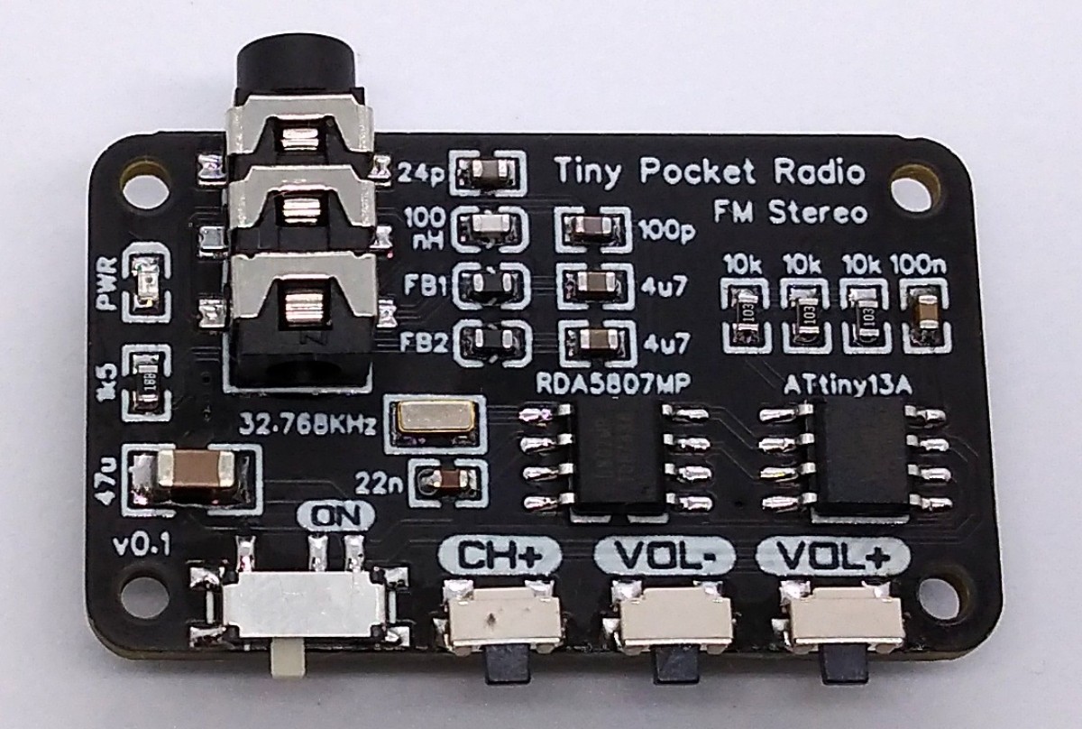
TinyPocketRadio is a simple FM stereo radio based on ATtiny13A and RDA5807MP. It's powered by a CR2032 coin cell battery and can drive 32 Ohm headphones via the 3.5 mm audio plug. The board size is 38 × 23 mm. It has a power switch and three buttons: "Channel+", Volume-" and "Volume+ ".
Hardware
The schematic is shown below Figure 1. All Design Files in EasyEDA: [1]
 |
||
| Figure 1. | The TinyPocketRadio schematic. | |
The low-cost RDA5807MP is a single-chip broadcast FM stereo radio tuner with fully integrated synthesizer, IF selectivity, RDS/RBDS and MPX decoder. The tuner uses the CMOS process, support multi-interface and require the least external component. All these make it very suitable for portable devices.
Software
I2C Implementation
The source code of the program is located in [2]. The I2C protocol implementation is based on a crude bitbanging method. It was specifically designed for the limited resources of ATtiny10 and ATtiny13, but should work with some other AVRs as well. Due to the low clock frequency of the CPU, it does not require any delays for correct timing. In order to save resources, only the basic functionalities which are needed for this application are implemented.
Controlling the RDA5807
The FM tuner IC RDA5807MP is controlled via I2C by the ATtiny. It has six writable 16-bit registers (addresses 0x02 - 0x07) and six readable 16-bit registers (addresses 0x0A - 0x0F). Since no data has to be read from the device for this application, only the writable registers are used. The RDA5807 has two methods of write access, a sequential one in which the registers are always written starting from address 0x02 and an indexed method in which the register address is transferred first and then the content. Both methods are determined by different I2C addresses. To transfer the 16-bit register content, the high byte is sent first. The RDA5807 is controlled by setting or clearing certain bits in the respective registers. The details of the meanings of the individual registers can be found in the data sheet. The current register contents are saved in the RDA_regs array.
Main Function
The code utilizes the sleep mode power down function to save power. The CPU wakes up on every button press by pin change interrupt, transmits the appropriate command via I2C to the RDA5807 and falls asleep again.
Compiling and Uploading
Since there is no ICSP header on the board, you have to program the ATtiny either before soldering using an SOP adapter, or after soldering using an EEPROM clip. The AVR Programmer Adapter can help with this.
If using the Arduino IDE
- Make sure you have installed MicroCore [3].
- Go to Tools -> Board -> MicroCore and select ATtiny13.
- Go to Tools and choose the following board options:
- Clock: 1.2 MHz internal osc.
- BOD: BOD disabled
- Timing: Micros disabled
- Connect your programmer to your PC and to the ATtiny.
- Go to Tools -> Programmer and select your ISP programmer (e.g. USBAsp).
- Go to Tools -> Burn Bootloader to burn the fuses.
- Open the TinyPocketRadio sketch and click Upload.
If using the precompiled hex-file
- Make sure you have installed avrdude [4].
- Connect your programmer to your PC and to the ATtiny.
- Open a terminal.
- Navigate to the folder with the hex-file.
- Execute the following command (if necessary replace "usbasp" with the programmer you use):
avrdude -c usbasp -p t13 -U lfuse:w:0x2a:m -U hfuse:w:0xff:m -U flash:w:main.hex
Links
- TinyPocketRadio design files
- The TinyPocketRadio source code
- MicroCore Arduino hardware package
- AVRDUDE command-line program