Because the 8-pin ATtinys only have a few GPIO pins available, they are usually operated without an external clock. The internal oscillator does a good job in most applications, but when it comes to precise timing, its ±10% accuracy is often insufficient. Fortunately, the oscillator can be calibrated, increasing its accuracy to ±2% or better. There are a few ways to perform this manual calibration, but several steps are required.
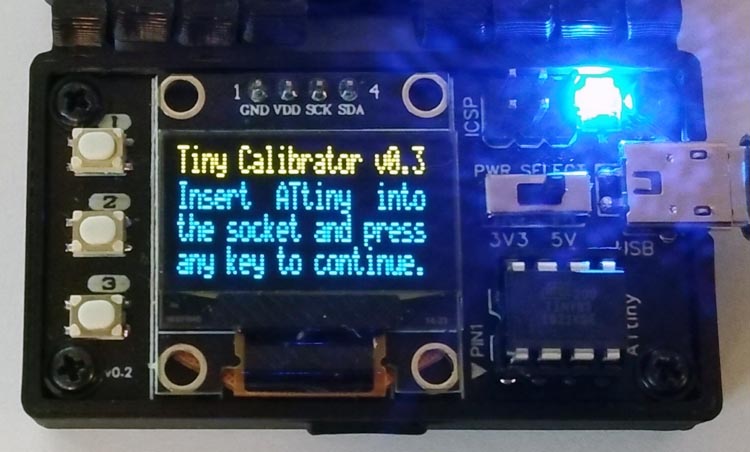
The TinyCalibrator does this fully automatically by a push of a button. In order to make the device more versatile, a high-voltage fuse resetter was also integrated, with which "bricked" ATtinys can be reset to the factory state.
 |
||
| Figure 1. | TinyCalibrator – OSC Calibrator and High-Voltage Fuse Resetter. | |
Hardware
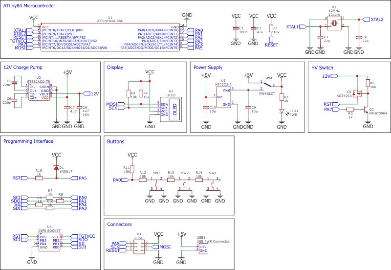
The TinyCalibrator is supplied with 5 V via a Micro USB connector. Since the frequency of the oscillator depends on the supply voltage of the ATtiny, an HT7333 voltage regulator was integrated. A switch can then be used to choose whether the oscillator should be calibrated for 3.3 V or 5 V.
The ATtiny84 was chosen as the microcontroller for the TinyCalibrator because it has exactly the necessary number of GPIO pins. For accurate frequency measurements, the ATtiny84 is operated with an external 12 MHz crystal. Since the current software version only requires about 3.7 KByte, an ATtiny44 can also be used.
 |
||
| Figure 2. | OSC Calibrator and High-Voltage Fuse Resetter Schematic Diagram. | |
To generate the 12 V for the High-Voltage Serial Programmer, an ST662A charge pump IC was chosen, which was specially designed for such applications and needs only a few external components. The 12 V is controlled by a MOSFET and applied to the RESET pin of the target ATtiny if necessary. The remaining programming lines to the target are protected against a short circuit with resistors.
The user interface utilizes three buttons and a 128×64 pixels OLED display. All project files available in download section and project page on Github.com [1].
Software
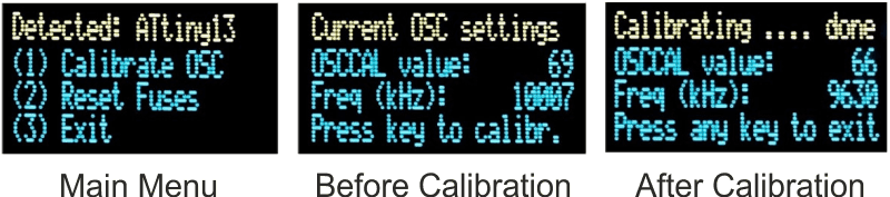
To carry out the calibration, a program is first uploaded to the target ATtiny using the integrated High-Voltage Serial Programmer. In addition, the factory oscillator calibration value (OSCCAL) is written to the EEPROM. The program on the target ATtiny reads the EEPROM and writes the value to the OSCCAL register. Then it applies an oscillating signal with half the clock frequency to pin PB0. Since the fuses were previously set so that the target ATtiny runs with a prescaler of 8, a signal with 1/16 of the oscillator frequency is applied to PB0.
This frequency is measured by the TinyCalibrator and compared with the target value. The oscillator calibration value (OSCCAL) is then adjusted accordingly and written to the EEPROM of the target ATtiny. This process is repeated until the OSCCAL value, which leads to the lowest frequency deviation, has been found.
 |
||
| Figure 3. | TinyCalibrator: Optimal OSCCAL value found. | |
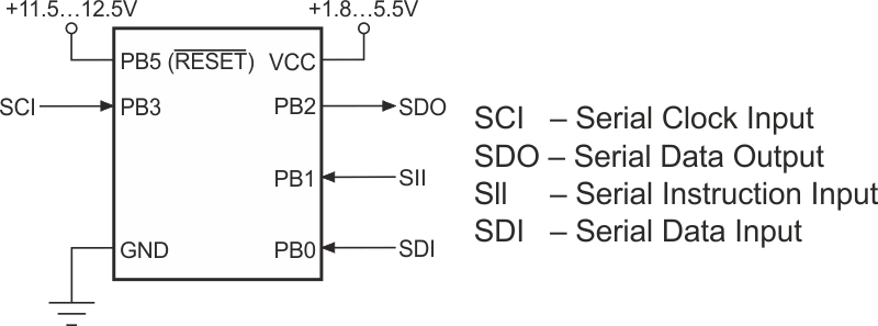
The code for the High-Voltage Serial Programmer (HVSP) is quite unspectacular. Simply put, for each action, a series of instructions are sent over the data lines to the target ATtiny and the corresponding response is read. The process and the instructions are well described in the data sheet.
 |
||
| Figure 4. | High Voltage Serial Programming Interface for AVR. | |
The timer/counters of the ATtiny84 are used for the frequency measurement. PB0 of the target ATtiny, which outputs a signal with 1/16 of its oscillator frequency, is connected to the T0 input of the ATtiny84. Timer0 counts the pulses at T0 and Timer1 stops the measurement after a time of 32 milliseconds. From this, the oscillator frequency of the target ATtiny can finally be calculated.
The I2C protocol implementation is based on a crude bitbanging method. It was specifically designed for the limited resources of ATtiny10 and Attiny13, but it works with some other AVRs (including the ATtiny84) as well. The functions for the OLED are adapted to the SSD1306 OLED module, but they can easily be modified to be used for other modules. In order to save resources, only the basic functionalities which are needed for this application are implemented. For a detailed information on the working principle of the I2C OLED implementation visit TinyOLEDdemo.
Compiling and Uploading
If using the Arduino IDE
- Make sure you have installed ATtinyCore [2].
- Go to Tools -> Board -> ATtinyCore and select ATtiny24/44/84(a) (No bootloader).
- Go to Tools and choose the following board options:
- Chip: ATtiny84(a)
- Clock: 12 MHz (external)
- Millis/Micros: disabled
- Leave the rest at the default settings
- Connect your programmer to your PC and to the ICSP header of the device.
- Go to Tools -> Programmer and select your ISP programmer (e.g. USBasp).
- Go to Tools -> Burn Bootloader to burn the fuses.
- Open TinyCalibrator sketch and click Upload.
If using the precompiled hex-file
- Make sure you have installed avrdude [3].
- Connect your programmer to your PC and to the ICSP header of the device.
- Open a terminal.
- Navigate to the folder with the hex-file.
- Execute the following command (if necessary replace "usbasp" with the programmer you use):
avrdude -c usbasp -p t84 -U lfuse:w:0xff:m -U hfuse:w:0xd5:m -U efuse:w:0xff:m -U flash:w:tinycalibrator.hex
If using the makefile (Linux/Mac)
- Make sure you have installed avr-gcc toolchain and avrdude.
- Connect your programmer to your PC and to the ICSP header of the device.
- Open the makefile and change the programmer if you are not using usbasp.
- Open a terminal.
- Navigate to the folder with the makefile and the Arduino sketch.
- Run "make install" to compile, burn the fuses and upload the firmware.
Operating Instructions
- Select the desired supply voltage (3.3 V or 5 V) with the switch.
- Connect a 5 V power supply to the micro USB port.
- Place the ATtiny13/25/45/85 in the IC socket and press any key. Use an SOP adapter for SMD parts.
- Select the function you want and follow the instructions on the display.
After the calibration process, the optimal OSCCAL value remains in memory address 0 of the EEPROM and can continue to be used. To do this, program the EEFUSE to preserve EEPROM memory through the chip erase cycle, otherwise the OSCCAL value will be lost after uploading new firmware. Your code should then contain the following function:
Of course, the OSCCAL value can also be set directly without the EEPROM. Remember that the OSCCAL value is displayed in hexadecimal (for example, OSCCAL = 0x66).