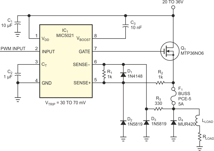
High efficiency and, hence, low loss is a usual design goal for a PWM circuit. Figure 1 shows one of several channels of low-loss PWM control for hydraulic valves used in heavy industrial machinery. These valves usually have dc resistance of approximately 12 Ω and substantial inductive reactance. The operating voltage is 24 V, and the PWM circuit usually operates at frequencies of 50 to 500 Hz to prevent valve sticking. To minimize on-resistance losses in the power MOSFET, the circuit uses a MTP36N06, even though that device’s current-handling capacity greatly exceeds the load requirements. A MIC5021 high-side driver provides gate control; its high slew rate minimizes the MOSFET’s switching losses. To implement the overload-protection feature in the gate driver, a low-resistance current-sensing resistor is necessary. Safety requirements and common sense mandate protection against catastrophic component failure. Unfortunately, the resistance of the fuse contributes to circuit losses. The combined losses in the fuse and current-sensing resistor are comparable with those in the rest of the circuit.
 |
|
| Figure 1. | A fuse does double duty as a protection device and a current-sensing resistor. |
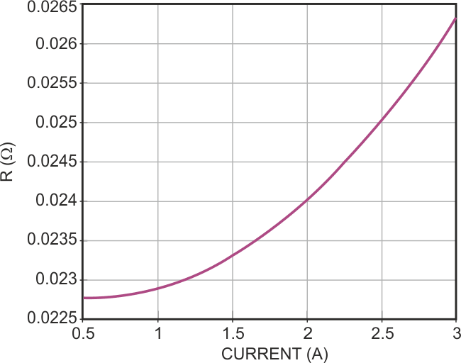
You can sometimes replace the current-sensing resistor by the fuse, thereby eliminating one of the two sources of loss. The dc resistance of a Buss PCE-5 5 A fuse is 20 to 30 mΩ, which is quite close to the value that the overload-protection circuit requires. The trip point of the MIC5021 overcurrent comparator is nominally 50 mV, but it may vary from 30 to 70 mV. Such wide tolerance makes setting a precise trip point with a precision resistor impossible. Another of the fuse’s benefits is its positive temperature coefficient of resistance. The comparator’s trip differential voltage also has a positive temperature coefficient. These two temperature coefficients track somewhat, offering some temperature compensation. Figure 2 plots the fuse-resistance behavior. The curve is an approximated mean value of resistance versus current. Data for the graph uses 10 samples of the fuse and a second-order polynomial function using Matlab software. According to Micrel’s data sheet, the trip point is a linear function of the ambient temperature.
 |
|
| Figure 2. | Self-heating causes a positive temperature coefficient of resistance in the fuse in Figure 1. |
R2 and R3, along with D2 and D3, provide protection against negative inductive-kick spikes at the comparator’s inputs. Adding R1 allows adjustment of the current trip point. D1 does not conduct during normal operation but protects the comparator from excessive differential voltage if the fuse fails. R2 and R3 limit the load current under this condition to a low and safe level. Disconnecting the fuse during experimentation leads to immediate shutdown, with only short (several-microsecond) pulses at the output. C2 determines the time between the circuit’s attempts to restart.