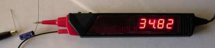
The Superprobe project was designed to see how much could be done with a PIC chip and just a few parts. The image at the right shows the capacitance measuring mode.
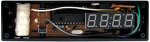
This device is designed around a PIC16F870 from Microchip, a 4 digit LED display module and very little else. Note: I have received a lot of inquiries on this project. To date, several have been duplicated world-wide. Many have been constructed in other types of cases. As long as the circuit is wired as shown, and the object code (below) is programmed into the PIC, the devices all worked perfectly.
Also note: If you try to use the object file and your programmer 'gags' on it, try removing the second to last line which is simply a chip type designator.
The LM2931 is a low drop out regulator. The regulator allows the unit to operate on 5 volts or as much a 30 volts. It also provides 30 volts of reverse polarity protection.
As you can see in the schematic even the usual resistors associated with driving the display have been eliminated. Usually, separate resistors need to be used in series with each segment drive in order to evenly drive the display. The PIC chip, however, limits the current flow to about 25 ma per line. The software is written in such a way that only one segment is active at any one time. This eliminates the effect of multiple segments having to share the same current source at the same time and dimming some digits more than others.
Various testing modes use the resistors in different ways. Unused resistors for any particular mode are removed from the circuit by having their pic pins floated. R5, for instance, is used for the logic pulser function. R4 is used to charge a capacitor to measure its value.
All of the original electronics were removed and one side was cutout for a piece of transparent red Plexiglass. The circuit was built up on pad-per-hole pref board.
Operation is via 2 pushbuttons. Holding down button #2 while pushing button #1 cycles through operating modes.....
|
Prob |
Logic Probe |
The logic probe shows 'H' for high (over 3.7 volts), 'L' for low (below 0.8 volts) and '-' for floating in the first display location. If a pulse is detected (0.5 usec minimum), the second location flashes a 'P'. |
|
PULS |
Logic Pulser |
The logic pulser shows the pulse rate (5, 50, 500, 5.0) in the last 3 locations. The first location shows the sensed logic level as a dash in the bottom or top of the digit. When button #1 is held down, a series of 0.5 microsecond pulses are generated in the opposite direction and the center segment is lit. Pushing button #2 cycles thru the 4 pulse rates. The selected pulse rate is saved on power down. |
|
FrEq |
Frequency Counter |
In the frequency counter mode, hitting button #1 switches the display to the next 4 digits of the count. For instance, the display shows '12.57' for a frequency of 12,576 hz. Holding down button #1 shows '2576' - the lowest 4 digits. If a decimal point shows, the value is in Khz, if the decimal is flashing, the value is in Mhz. Hence, a frequency of 42,345,678 hz is displayed as 42.34 with a flashing decimal. Holding down button #1 in this case will display 5678. |
|
Cnt |
Event Counter |
In the event count mode, the display shows the lowest 4 digits. Button #1 switches to the next higher 4 digits while held down. Button #2 resets the count. |
|
VoLt |
Voltmeter |
The voltmeter uses the power going into the probe as a voltage reference. The current implementation shows only an approximate voltage - about 2% high. This can still be very useful for most measurements. Do not connect the probe to voltages that exceed 5 volts under any conditions. |
|
diod |
Diode Junction Voltage |
This is just the voltmeter function with 10k resistor feeding current to the probe tip. When a diode or transistor junction is connected from the tip to the ground lead, the drop voltage is displayed. |
|
Cap |
Capacitance Measurement |
When a capacitor is connected from the tip to the ground lead, and button #1 is pushed, its value is displayed. Values from .001 uf to about 500 uf are displayed. The larger the capacitor, the longer it takes to measure. A value of 100uf takes a couple of seconds. |
|
Coil |
Inductance Measurement |
When an inductor is connected from the tip to the ground lead, and button #1 is pushed, its value is displayed. Values from 0.1 to 999.9 millihenries are displayed. Note: this function assumes that the DC resistance is not more than a few ohms. Also, if the unit gets 'stuck' in this mode, jumper the tip to ground to free it. |
|
SIG |
Signal Generator |
This mode generates a 500hz square wave at about 0.5 volts. The signal is only generated while button #1 is held down. |
|
ntSC |
Video Pattern |
Generates an NTSC video frame with a white dot pattern when button #1 is held down. |
|
9600 |
Serial Ascii |
Each time button 1 is pushed, the letters A-Z followed by cr/lf is generated. Auto polarity sensing. If the signal injection point is originally high, then normal (zero start bit) ascii is generated. Otherwise, the other polarity is done. New feature: Button #2 cycles thru 1200, 2400, 4800, 9600 baud. |
|
Midi |
Midi Note |
Sends note number 60 (middle C) on any of the 16 midi channels. Holding button 1 sends 'note on'. Release of button 1 sends 'note off'. Button 2 cycles thru the 16 channels. The midi channel number is stored. |
|
R/C |
R/C Servo |
Generates 1ms to 2ms pulse for r/c servos. Button 1 increases pulse, Button 2 decreases pulse. Defaults to 1.5 ms each time mode is entered. |
|
[ ] |
Square Wave |
Generates 1 - 9999 hz square wave. Button 1 decreases frequency, Button 2 increases frequency. |
|
Prn |
Pseudo Random Number |
Generates 10khz digital PRN series. |
|
ir38 |
IR LED |
Generates 1 millisecond on and 2.5 millisecond off of 38khz square wave. When connected to IR LED, used for testing IR receiver modules. |
|
PWM |
Pulse |
Generates variable pulse width 3-97 percent of a 6khz (approx) digital signal. Button 1 decreases pulse width, Button 2 increases pulse width. |
In any mode, holding down both buttons exits to the menu. Once there, releasing and pressing button #1 cycles thru its modes forward. New Feature: Button #2 cycles thru modes backwards.
The mode is saved on power down. Since this device takes its power from the circuit being tested, powering down and back up will restore the same operating mode.