You can use a microcontroller that includes an ADC to design a two-wire-plus-ground keyboard interface. For example, you can use a resistive voltage divider to identify a pressed key (Reference 1). A microcontroller's integrated ADC typically presents an input resistance on the order of hundreds of kilohms, and, for adequate accuracy, its keypad divider should comprise relatively low-value resistors of 10s of kilohms. However, in battery-powered systems, a resistive divider can consume a few hundred microamperes, forcing a designer to choose an alternative classic digital-matrix array of switches and multiple I/O lines. Moreover, portable-equipment designs typically place constraints on the number of components.
 |
|
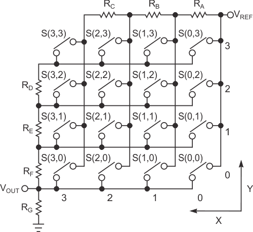
| Figure 1. | A two-wire resistive voltage-divider interface encodes a four-row-by- four-column keypad. |
To satisfy both requirements, the circuit in Figure 1 uses a matrix keypad and a resistor network divided into two row and column sections. For the four-by-four-key keypad, seven resistors are sufficient to encode any pressed key, and the circuit consumes power only while a key remains closed. Conversely, with no keys pressed, the standby current approaches zero. Using only two values of resistors, let RA = RB = RC = R1 and RD = RE = RF = RG = R2. Assigning values from zero to three for the keys' x and y addresses, you can calculate the voltage across resistor RG for any key closure by solving the following equation:
Driving the resistor array from VREF, the ADC's reference voltage, allows you to perform a ratiometric conversion that eliminates errors in key encoding due to fluctuations in VREF.
The following equation describes the voltage-division ratio, r(x,y), for any keystroke:
The ratio p = R1/R2 represents the ratio between row- and column-group resistors' values. For p = 4, you calculate 16 values of r(x,y), in the [1/16, 1] range, as a function of the pressed key's position. In general, the minimum difference between r partitioning ratios occurs for the nearest keys as the (3,2) and (3,3) x,y indexes indicate. For an N-bit ADC and a ratio of p = 4, the ADC should have a resolution that satisfies the following equation:

Note that the reciprocal of 240 (0.0041…) exceeds the reciprocal of 28, and the circuit thus requires an ADC capable of at least 8-bit resolution (N ≥ 8 bits).
Unfortunately, standard-value components with nominal tolerance, T, cannot provide an ideal solution to this equation. Instead, you calculate a partitioning-ratio difference, d = r(3,2) – r(3,3), for the worst-case condition. The lowest value of d occurs for a minimum value of RG and RD and the maximum value of RA, RB, RC, RE, and RF. You can account for all the resistors' values and define a generic ratio, p, for the nominal values of R1 and R2:
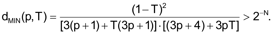
The same value of T applies to all resistors. If n = 8 and p = 4, the previous equation yields a solution of T < 0.018, which indicates that resistors of ±1% tolerance correctly encode 16 keys. Moreover, if you now impose the chosen fixed tolerance, T, you can solve the equation to obtain the required limit on the p ratio between the values of R1 and R2. If T = 0.01, the solution to the equation becomes p < 4.074.
 |
|
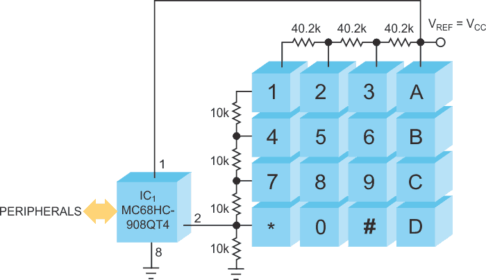
| Figure 2. | Using the microcontroller’s analog reference-voltage output and ratiometric analog-to- digital conversion ensures correct encoding of the keypad. |
The circuit in Figure 2 uses NXP’s Nitron MC68HC908QT4 microprocessor, which serves as a test bed for a keypad based on the above-calculated values, and uses power-supply voltage VCC as the resistor matrix's reference voltage, VREF. To satisfy the requirement for p (4.074 > p > 4), use R1 = 10 kΩ±1% tolerance and R2 = 40.2 kΩ±1% tolerance, both standard values that the E48 series offers. Table 1 lists output codes corresponding to 16 individually pressed keys, and Table 2 lists data obtained when simultaneously pressing two keys and illustrates that two-key combinations can evoke special functions.
| Table 1. | Single-key output codes | ||||||||||||||||||||||||||||||||||||||||
|
|||||||||||||||||||||||||||||||||||||||||
If your application requires a microcontroller that lacks an internal interrupt that the ADC generates, you can connect an external comparator to the output voltage in Figure 1. Set the comparator's threshold lower than the lowest voltage developed at the output voltage – approximately VREF divided by 16 in the example – and the comparator's output serves as a keypad-interrupt source for the microcontroller.
| Table 2. | Two-key output codes | ||||||||||||||||||||||
|
|||||||||||||||||||||||
Note that a microcontroller with a 10-bit ADC, such as a NXP MC68HC908QB or a Texas Instruments MSP430F11 can service a five-row by six-column keypad matrix encoded by 10 resistors. Repeating the analysis shows that a row-to-column p ratio of 5 to 5.51 and a required resistor tolerance of less than 4.3% correctly encode the keys. You can use values of 10 kΩ for R1 and 51.1 kΩ or 53.6 kΩ for R2 of the ±1%-tolerance E48 series.