Nonlinear systems often need to become linear to be useful, and the circuit in Figure 1 provides a nonlinear sawtooth pulse for a PWM (pulse-width modulator) that can compensate for nonlinearities in sensors, controllers, or systems. The circuit outputs a linear sawtooth pulse, a quadratic parabolic pulse, and a cubic parabolic pulse of equal and constant width following an external trigger pulse. All pulses have equal peak amplitudes.
 |
|
| Figure 1. | This triggered circuit generates linear, quadratic parabolic, and cubic parabolic pulses, all starting from 0 V and having equal peak-level magnitudes. |
The circuit incorporates a cascade of three synchronously switched integrators. IC3’s S2D2 switch switches the input of integrator IC2D, the first in the chain, to the source of reference voltage VREF. You need two integrators employing IC2D and IC2C to generate a quadratic parabolic pulse. The third integrator, using IC2B, lets you simultaneously generate a cubic parabolic pulse. Each integrator has a series input switch and a reset switch that connects in parallel with a respective integrating capacitor.
The S1AD1 switch in IC4 is a reset switch for integrator IC2D. The complementary S1BD1 switch serves as a series input switch for integrator IC2D. Similarly, the S2AD2 switch is a reset switch for integrator IC2C. The S2BD2 switch is a series input switch for integrator IC2C. The positions of all switches are at logic high at all control inputs: IN1 to IN4 of IC3 and IN1 and IN2 of IC4.
Integrators IC2D and IC2C also have input-grounding switches in IC3, S1D1, and S3D3, respectively. The grounding switches ensure that error due to leakage currents of the series switches is approximately 50% less than that of a design not using the grounding switches.
The Integrate logic signal controls all series switches. When the signal is high, it turns on all the reset and grounding switches. Thus, integrators IC2B, IC2C, and IC2D are either integrating their respective analog input signals or resetting to a 0 V output. The input of integrator IC2D switches to the output of precision voltage-reference cell IC2A. Thus, signal VOUTL becomes a negative sawtooth pulse. The pulse varies within its duration, T1, as:
Inverter IC2A inverts this pulse. IC2A has a voltage gain of negative one because positive pulses are more common. Integrator IC2B integrates sawtooth pulse VOUTL; IC2B therefore outputs a quadratic parabolic pulse:
The equation describes a pulse that integrator IC2B simultaneously integrates, producing a cubic parabolic pulse:
VOUTLPEAK, VOUTQPEAK, and VOUTCPEAK are negative or positive voltage peaks at the outputs of their respective integrators. T1 is the width of the Integrate pulse. Theoretically, to achieve VREF = VOUTLPEAK = VOUTQPEAK = VOUTCPEAK, you must stagger the integrating time constants of the respective integrators as 1-to-1/2-to- 1/3, respectively. In this case, however, VREF = 3 V, whereas VOUTLPEAK = VOUTQPEAK = VOUTCPEAK = 5 V.
You must multiply the 1 in the staggering ratio by 3/5. Considering the time constant of integrator IC2C, you get a stagger ratio of 6/5-to-1-to-2/3. For the equal values of integrating resistors RIL = RIQ = RIC, this staggering holds true for the values of respective integrating capacitors. The circuit uses a high-quality, SMD (surface-mount- device) ceramic capacitor, CIQ, with a value of 2.3692 nF. To achieve the necessary precision staggering, CIL comprises 2.4016-nF, 343-pF, and 79-pF capacitors in parallel. CIC is a parallel combination of 1067 pF and 499 pF.
 |
|
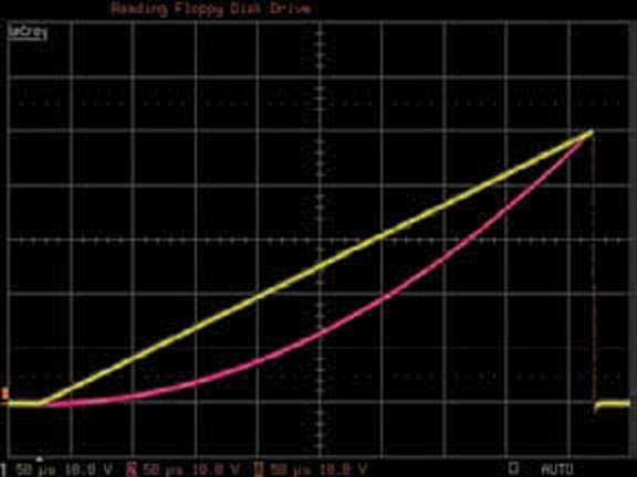
| Figure 2. | At the midwidth of the pulse, the quadratic parabolic pulse’s voltage level (pink trace) is exactly one-fourth of its peak level. |
A rising edge at the trigger input forces the Integrate signal low, which turns off the reset and grounding switches and turns on the series switches. The integration lasts until VOUTQPEAK = 5 V, forcing the output of IC5 low, which in turn sets Integrate high. Thus, the series switches are off, and the reset and grounding switches are on. The circuit remains in this steady state until the next rising edge at the trigger input. The Analog Devices ADG1213 and ADG1236 switches work well in this design because of their charge injection of 1 pC or less. Figure 2 shows the circuit’s high precision, depicting linear and quadratic-parabolic-pulse shapes.