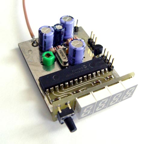
This is a successor of the PIC16C71 4-digit LED f-counter & V-meter. Some hard to find parts used in the previous version, which are out of production for some time, has been omitted. A rather early PIC16C71 has also been replaced by 28-pin device PIC16F876. The later is capable of driving 4 digit LED display in multiplexed mode while measuring frequency, power supply voltage as well as handle two analog inputs to display SWR/PWR signal strength in a bargraph manner. There is no need for external LED display driver chip as well as external data EEPROM since it is already implemented in PIC16F876. Reduction in the number of used chips also results in smaller dimensions of the counter compared to its predecessor.
 Click to enlarge |
| Circuit schematic |
 Click to enlarge |
| PCB |
 |
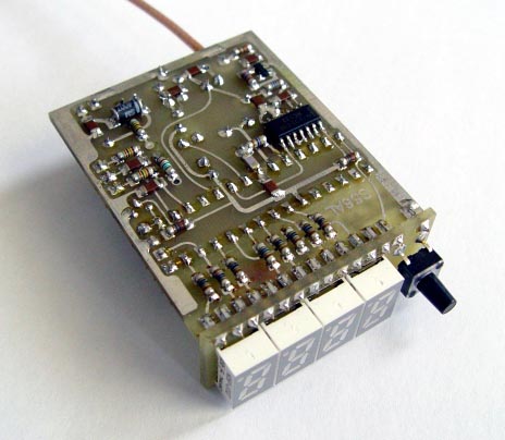 |
| Latest PCB version | |
The latest software version (V1.1) supports following functionality:
- Measurement of the frequency up to 50MHz
- Measurement of power supply voltage in the range of 0.0 V … 25.5 V
- Measurement of the input voltage at two analog inputs, simultaneously displayed as bargraph (PWR/SWR or S) indicator. The input sensitivity could be chosen between 0.25V, 0.5V, 1.0V and 2.0V for maximum bargraph indication.
- Power save mode: Automatic display shut-down in case the push-button action or frequency change does not occur for a certain time. Display switches on again after frequency change or push-button action. The available shut-down time periods are 3s, 10s, 30s, 60s, 120s, 180s and 240s. This function can be disabled in set-up menu.
- Programmable frequency offset added or subtracted from measured frequency, settable in the range of 0 to 99,999.9 kHz. This is convenient for use with heterodyne type of RX/TX
- Different display modes: XX.XX MHz, X.XXX MHz, XXX.X kHz
- Display resolution 100 Hz
- Measurement resolution 12,5 Hz
- Hysteresis of displayed value 25 Hz
In operating mode a push-button allows the user to choose between the frequency, bargraph or supply voltage to be displayed. The frequency display mode can also be changed with longer (>1s) push-button pressing. For example if the frequency to be displayed is 14.065.9 MHz the user will see on the four digit display either "065.9", "4.065" or "14.06". The default display mode after power-up can be changed in the set-up menu. The set-up menu is entered at power-up while holding the push-button pressed.
The production of Siemens's (now Infineon's) miniature 7 seg. LED HDN1077 displays in low current version (suffix O) was abandoned recently. Therefore I've designed another display PCBoard which suits the same f-counter base board but uses newer Agilent's HDSP-U103 miniature 7 seg. LED displays. Their current consumption is even smaller. They need no more than 0,5mA per segment for acceptable brightness. Assuming that during normal operation in average only one half of the segments lights, the average current consumption of the counter is about 20mA. In power-save mode the consumption reduces to less than 10mA which is important in case of battery powered equipment.
The latest software version of the frequency counter is for radio-amateur and non-commercial use downloadable from this page for free. The PIC controller is in-circuit programmable if the MC34064 reset circuit is not soldered to the PCB. The instalation of this IC is strongly recommended after the frequency counter has been built and tested.
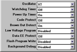 |
| PIC config bits |
Downloads:
HEX code, V1.11 (operates with 4,000 MHz quartz)
Hex code, V1.12 (operates with 4,1943 MHz quartz)