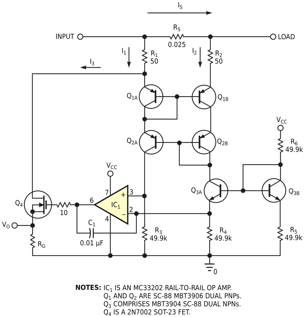
The accurate, high-side, current-sense circuit in Figure 1 does not use a dedicated, isolated supply voltage, as some schemes do. Only the selected transistors limit the common-mode range. The circuit measures the voltage across a small current-sense resistor, RS. The operation of the circuit revolves around the high-side current mirror comprising Q1 and Q2. All the circuit components have one overall function: to make the collector currents equal in Q1 and Q2. The additional current mirror using Q3 sets the values of the collector currents. The collector current is
You can best calculate the gain of the circuit by analyzing the loop formed by R1, RS, R2, Q1B (emitter base), and Q1A (base emitter). In Figure 1, the currents are IS, the high-side measurement current; I1 and I2, the mirror currents of Q1A and Q1B; and I3, a branch current from the emitter of Q1A.
 |
|
| Figure 1. | This circuit measures high-side currents without the need for auxiliary power supplies. |
When you sum the currents around the loop,
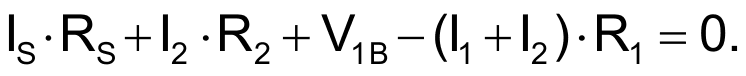
Because I1 = I2, R1 = R2, and the emitter-base voltages are equal,
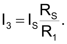
Looking at the remaining circuitry, the op amp keeps the transistors' collector currents equal by controlling I3 through Q4. Therefore, the overall transfer function is
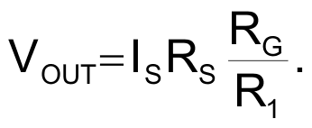
For RG = 1 kΩ, the transfer function is VOUT = 0.5•IS. The circuit can operate over a common-mode input range of approximately 10 V to several hundred volts, limited by the selected transistors.