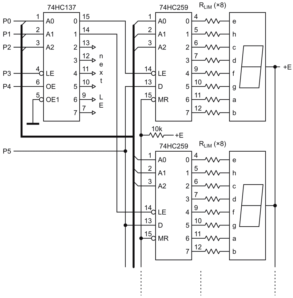
This expandable LED display for a microcontroller in Figure 1 has a simple interface with only 6 data/control wires and can be easily accommodated to a DIY design. The display has static indication.
 |
|
| Figure 1. | The expandable LED display for a microcontroller has a relatively simple interface with only 6 data/ control wires. |
The main parameters are:
- Digits: 8 Hex digits (may be more, expandable)
- Data & control wires: 6 (minimum)
- Power voltage: 3…6 V
- Power consumption: < 3…5 mA/digit (RLIM in range 2 k – 2.4 k for E = 3.3 V or, RLIM in range 4.3 k – 5.1 k for E = 5 V)
If you choose the segment current too low (lower than ~0.7 mA) some segments may become much darker than others. For this reason, it would be wise to check the performance of your indicators with the low current.
The circuit in Figure 1 is optimized for 7 segment indicators such as the A-522SR (dual, with common anode and super-bright LEDs) and DIP versions of the 74HC259 (8-bit addressable latch) and 74HC137 (decoder).
By placing the pair latch/indicator in close vicinity to one another, we can strongly reduce not only the dimensions of the display, but the amount of soldering as well. This characteristic makes the circuit very suitable for DIY designs. In this design, we can solder the RLIM resistors (SMD 0805) directly between the corresponding legs of the latch and indicator. The pin assignment is shown for this case.
The algorithm static LED display: Initial/displaying state: P3=1, P4=0, all other pins are of no importance.
The steps required to change the data on the display are as follows:
- Set a digit’s address: P2…P0 = address
- P3 = negative strobe 1-0-1 to latch the address
- Set a segment’s address: P2…P0 = address
- Set a value of D: P5 = 0 if the segment must be ON, P5 = 1 if OFF
- P4 = positive strobe 0-1-0 to latch the value of D
- For all the other segments, repeat from starting from step 3. When all the segments are done, go to step 1 while there are unattended digits.
This principle can be expanded for more digits simply using an analogous decoder with more legs.