Many applications involve the digital synthesis of three-phase sinusoidal waveforms, such as ac-motor drives, active power filters, and grid-voltage synchronizers, that use a microcontroller or a DSP for digital control. You can perform this synthesis by using conventional analog techniques (Reference 1) or DDS (direct digital synthesis). Digital techniques provide higher stability and the ability to incorporate frequency, phase, and amplitude adjustments. For applications requiring 16-bit or higher-resolution, three-phase-signal synthesis, DDS involves the use of a microprocessor or a DSP to interface multiple DACs. This approach uses not only a lot of devices, but also supporting components and board space. Although one device can have multiple-output serial-controlled DACs with four, eight, 32, or more channels, the DACs provide few bits at the expense of the number of channels. Hence, using multiple-output DACs is an unappealing approach.
Alternatively, you can use shift registers or switched-capacitor filters, but this approach also involves a high parts count, and the lack of phase and amplitude adjustment makes this method inappropriate for high-resolution DDS (Reference 2). In contrast, stereo DACs are readily available. Their widespread use has produced low-cost, high-quality components. For example, the NXP UDA1330ATS has an I2S-serial data-format interface; word lengths of 16, 18, and 20 bits; and sampling frequencies of 8 to 55 kHz. These features make the DACs attractive for three-phase DDS with few components.
This Design Idea implements DDS techniques using an ARM microcontroller, IC1; one stereo-DAC, IC2; and one op amp, IC3 (Figure 1). The ARM AT91SAM7X256 code in Listing 1 generates a table containing the cosine function of the desired resolution and length. The table produces cos(α + 2/3π) and cos(α – 2/3π). The ARM microcontroller sends the data using I2S-serial format by using interrupts attaching the ISR (interrupt-service routine) whenever the output buffer is empty. Listing 2 shows how to achieve an ISR to send the data. IC2 provides voltage outputs VA and VB, which are two of the three signals for a maximum amplitude of 5 V p-p, but with an offset of 2.5 V. You can derive the third channel as a function of the other channels. You can easily implement this operation using a single inverting, summing op amp, IC3, and the 2.5 V DAC reference for canceling the offset. In this case, RF = RA = RB = 10 kΩ for obtaining unity gain, and you could add a potentiometer in the inverting pin for an exact offset cancellation if the resistors don’t match exactly.
 |
|
| Figure 1. | This scheme implements three-phase DDS (direct digital synthesis) with few components. The code in the ARM processor provides the ability to incorporate arbitrary frequency, phase, and amplitude adjustments with 16-, 18-, or 20-bit resolution. |
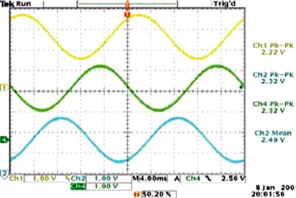
Figure 2 shows the synthesis of the three-phase waveforms. A design tip to have in mind is that, due to the use of the I2S interface, the outputs have an inherent phase delay. You can neglect this delay, of exactly 1/fs, for audio applications, but it could matter in power systems. The straightforward approach to this delay is to synthesize the second channel with a negative phase delay that compensates the inherent delay. Figure 2 shows no phase delay between the output channels, except the 120° relative phase between them. Because only 120° relative phase difference is necessary, signals other than pure sinusoidal can be output. Moreover, active power filters can benefit from a high-order-harmonics, three-face reference signal.
 |
|
| Figure 2. | Traces 1 and 2 show the voltage outputs from the DAC. Trace 4 is the third channel that an inverting, summing op amp provides. |
References
- Dutcher, Al, “Inverters form three-phase VCO.”
- Perez-Lobato, Eduardo, “Three-phase sinusoidal-waveform generator uses PLD.”