In the classic configuration and most variants of the astable 555 multivibrator circuit, the timing characteristics are based on the charging and discharging of a capacitor. However, it can be argued that since the exponential voltage of a capacitor is qualitatively similar to inductor current, the latter can be made an alternative timing element for the 555. This was shown in the Reference 1. In Figure 1, we present another approach for an inductor-based astable 555 multivibrator.
 |
| Figure 1. |
An astable 555 timer circuit based on an inductor, diode, and resistor. |
At power-on, the inductor voltage (VL) spikes up and exceeds the 555’s trigger voltage of 2VCC/3. Output (VO) at pin 3 goes low and the discharge transistor at pin 7 turns on which provides a low-resistance path to ground. Inductor current (IL) begins to rise as VL and the voltage at pin 2 (V2) and pin 6 (V6) all fall exponentially.
When V6 gets below the 555’s threshold voltage of VCC/3, VO goes high, and the discharge transistor turns off. Because IL was interrupted, the inductor’s voltage reverses which forward-biases the flywheel diode (D). Pin 7 gets clamped to a diode forward voltage above VCC. Both IL and VL start to fall towards zero while V2 climbs toward VCC.
When V2 crosses 2VCC/3 again, VO goes low, the discharge transistor turns on, and the train of regular high and low output pulses ensues. The expected waveforms are shown in Figure 2.
 |
| Figure 2. |
The simulated waveforms using Tinkercad (setting: 15 µs/div). |
For each state of VO, we derived the first-order differential equation of the effective circuit. This led us to the Equation 1 for calculating the pulse widths:
| |
 |
(1) |
The symbols are defined in Table 1 where the columns for TH and TL list specific values that the symbols take on. We also considered RS as the in ductor’s DC resistance, RON = 59.135/VCC0.8101 as the resistance of the discharge transistor at pin 7 (Reference 2), and VD = 0.6 V as the diode forward voltage.
| Table 1. |
Formulas to predict timing characteristics |
| Symbol |
Definition |
High Time (TH) |
Low Time (TL) |
| R |
Equiv. resistance |
R1 + RS |
R1 + RS + RON |
| II |
Initial current |
2VCC/(3R1) |
VCC/(3R1) |
| IF |
Final current |
VCC/(3R1) |
2VCC/(3R1) |
| t |
Time constant |
L/(R1 + RS) |
L/(R1 + RS + RON) |
| VS |
Voltage “seen” by R-L |
–VD |
VCC |
|
To test these ideas, we prepared a spreadsheet calculator that predicts TH, TL, and other output characteristics. Then we picked the components listed in Table 2, used a digital LCR tester (SZBJ BM4070) to measure their actual values, and plugged the numbers into the calculator. The predicted attributes of VO are listed in Table 3.
| Table 2. |
Components for the experimental circuit |
| Component |
Commercial
value |
Measured
value |
| R1 (Ω) |
390 |
387 |
| L (mH) |
18 |
17.48 |
| RS (Ω) |
N/A |
123 |
|
| |
| Table 3. |
Predicted versus measured values (VCC = 5.00 volts) |
| VO characteristics |
Predicted |
Measured |
% Difference |
| Time_High (µs) |
19.868 |
20.354 |
2.42 |
| Time_Low (µs) |
58.588 |
63.800 |
8.52 |
| Period (µs) |
78.456 |
84.154 |
7.01 |
| Frequency (kHz) |
12.746 |
11.883 |
7.01 |
| Duty_High (%) |
25.323 |
24.187 |
4.59 |
|
| |
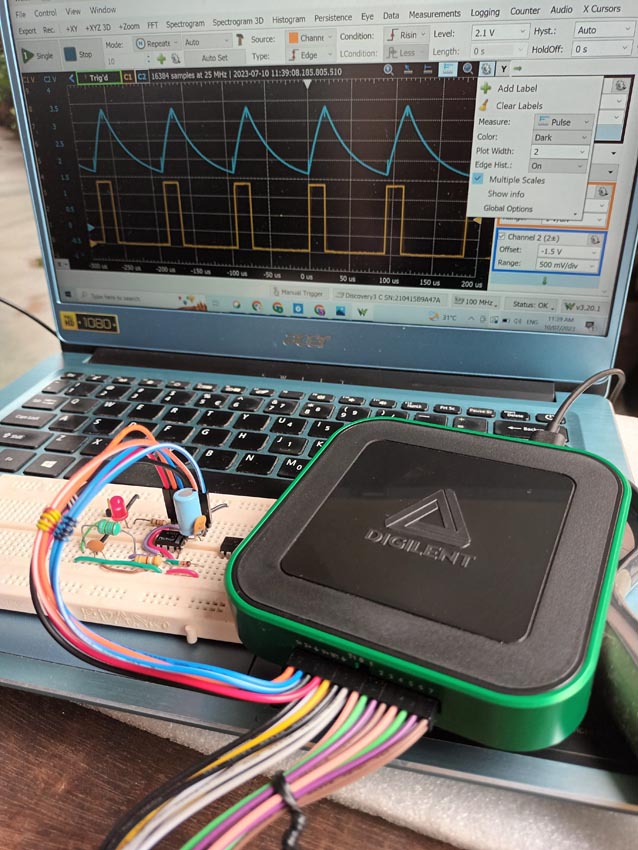 |
| Figure 3. |
Experimental set-up with the Digilent Analog Discovery 3
connected to the +5 V to the experimental circuit. |
Finally, we connected to our laptop, a USB-powered test and measurement device – the Digilent Analog Discovery 3 (AD3) – to supply +5 V to the experimental circuit (Figure 3) and observe the waveforms from pins 2 and 6, and 3 of the IC (Figure 4). We tested 8 chips from a bin of assorted 555s and noticed that while TH was consistent, the TL values annoyingly lacked precision. Nonetheless when we compared the AD3 Measurements with the Predicted values in Table 3, we saw that Equation 1 fairly modeled the output of the new multivibrator.
 |
| Figure 4. |
Waveforms of V2, V6, and VO, and measurements for VO. |
References
- Arthur Edang. “Inductor-based astable 555 timer circuit.“
- Phil Rogers. "Design low-duty-cycle timer circuits."
Materials on the topic
- Datasheet Texas Instruments LM555CN/NOPB