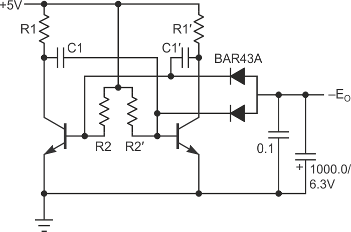
Here is the circuit in Figure 1 from a previous DI (Ref. 1):
 |
|
| Figure 1. | Simple local low-noise voltage converter that can be used when a simple negative supply of low voltage is required. |
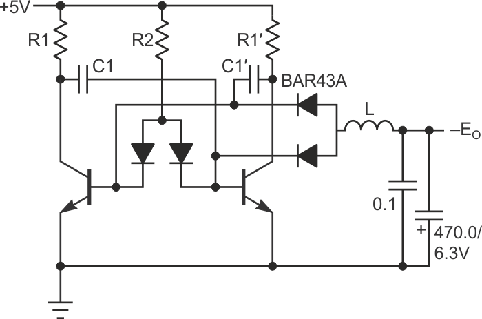
It is simple, and its efficiency can be improved by a very quick change. If you fix both values of R1 and R1′ (making the input power fixed also), the output voltage will have an extremum on the graph EO = EO(R2). To facilitate the achievement of this extremum the circuit Figure 1 can be modified as shown in Figure 2; here you can change the value of both R2/R2’ with a single potentiometer (R2).
But the main alteration is in adding inductance L to the output. A rather low value of inductance (0.1…1.0 mH) is sufficient. (This low value may be counter-intuitive to the low frequency of the multivibrator, which is less than 1 kHz.)
The negative output voltage slowly increases with an increasing inductance: from –0.36 V @ L = 0.1 mH to –0.4 V @ L = 1 mH.
The main advantage is in this ~25% increase of the output current (voltage). While the circuit in Figure 1 has its maximum output voltage at –0.31 V, the circuit Figure 2 can provide more than –0.39 V with the same load (910 Ω).
This increasing is due to… hmmm…we’ll see the explanation in comments…
The second improvement is in output noise: the same inductance L significantly decreases it – the output capacitor in Figure 2 has half the capacity, nevertheless the amplitude of the output noise here is halved.
 |
|
| Figure 2. | Added inductance to the output of Figure 1 to improve converter efficiency. |
The values of components are: L = 0.1…1.0 mH, R1 = R1’ = 5.6 k, R2 = ~22 k, C1 = C1’ = 0.1 µF. The output capacitors should be of low impedance.
The circuit consumes less than 1.5 mA from +5 V and produces more than –0.39 V on 910 Ω load. The very first circuit (Ref. 2) with the same output current consumes about 10 times more power, but its output noise is about 100 times less.
With all these circuits there may be one problem though: they produce a low voltage which is not critical for the host system, but if it somehow drops, the results will be distorted and this can be unnoticed.
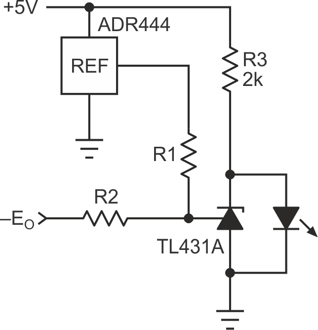
To make sure any drop of this voltage will be detected, a circuit in Figure 3 can be used. It can be useful to monitor the coherence of the power in any system with dual power.
 |
|
| Figure 3. | Circuit that ensures any drop is voltage is detected that may result in distorted results for converters in Figure 1 and Figure 2. |
The green LED indicates “Power Good” and can be used as “Power On” indicator for the whole host system. The resistors R1, R2 should be stable 1% at least. The LED should go on when the output voltage grows to e = –20…–100 mV, depending on your buffer parameters.
For values R1, R2 let:
VR1 = VREF + |e|,
VR2 = 2.5 + |e|,
then

For the given reference and e = 50 mV:
R1 = 0.63 × R2.
For example, R1 = 38.8 k, R2 = 62 k. These values may call for some trim because their total value cannot be too low – the output current should be used sparingly. And the input current of TL431 has far more influence when the current through the voltage divider is very low, so some trim is recommended in this case. Finally, any other reference with output voltage more than 2.5 V can be used, but the values of R1, R2 should be recalculated.
References
- Demchenko, Peter. “Multivibrator also makes true-zero output of the op-amp.“
- Demchenko, Peter. “Photocell makes true-zero output of the op-amp.“