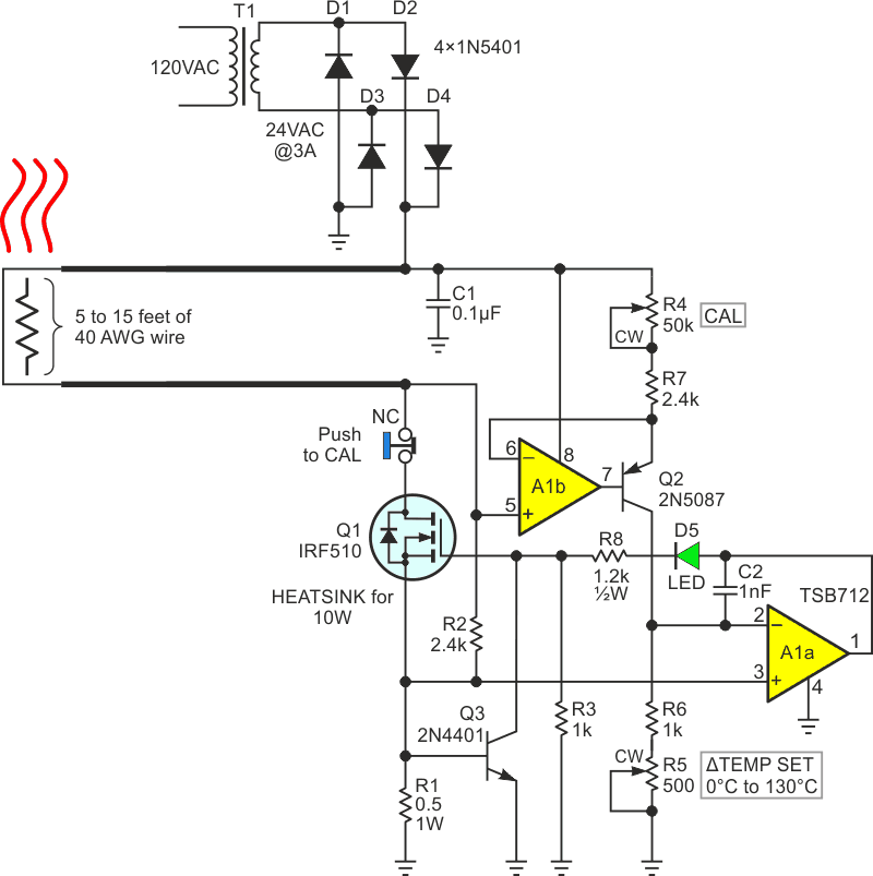
Conventional thermostats are based on separate temperature sensor and heater devices with means for feedback between them. But in some recent EDN design ideas (DIs) we’ve seen thermostat designs that meld the functions of sensor and heater into a single active device (usually FET or BJT). The ploy can make a better fit to applications where the intended thermal load is physically small or has some other quirk of geometry that makes it inconvenient to apply the classic separate sensor/heater schema. This DI (see the Figure 1) follows the melded concept but takes it in a somewhat different direction by using fine gauge copper wire (e.g., 40 AWG polyurethane insulated) as an integrated temperature sensor and heater.
 |
|
| Figure 1. | Miniature thermostat utilizing the tempco and I2R heating of 40 AWG copper wire as a melded sensor/heater. |
Here’s how it works.
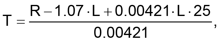
The resistance and temperature coefficient of a standard 40 AWG copper wire at 25 °C are generally spec’d at 1.07 Ω/foot and +0.393 %/°C, respectively. Therefore, L feet of 40 ga can be expected to have an approximate resistance at a given temperature T of:
 |
(1) |
 |
(2) |
 |
(3) |
 |
(4) |
Equation 4 holds well from R/L = 0.965 Ω/ft at 0° up to 1.6 Ω/ft at 155° (the recommended upper temperature limit for solderable polyurethane wire insulation).
Consider the implications for the use of fine copper wire as a combination temperature sensor and heater.
If a suitable length (between 5 and 15 feet) of wire is placed in a feedback loop driving current through it so as to dissipate enough I2R heating to raise and maintain a temperature that creates a preselected constant wire resistance, then said temperature, and the temperature of any thermal load thermally bonded to it, would likewise be constant! This is exactly what the circuit in the figure does.
Q1’s drain supplies heating; heating current I to the sensor/heater wire (please ignore for a moment the minor contribution from start-up resistor R2). The voltage induced between the terminals of the R wire resistance is then:
 |
(5) |
This causes the A1b, Q2 current source to output:
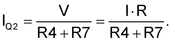 |
(6) |
Which induces a voltage at pin 2 of A1a:
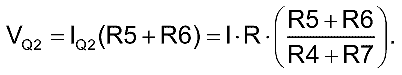 |
(7) |
Meanwhile, Q1’s source current (also equal to I) sampling resistor R1 produces:
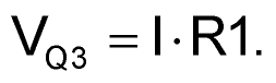 |
(8) |
FET control amplifer A1a forces FET gate voltage and thereby R drive current such that:
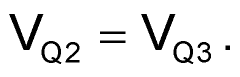 |
(9) |
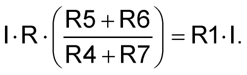 |
(10) |
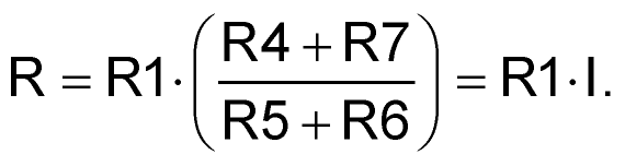 |
(11) |
Thus, heater current, and therefore wire resistance and temperature, are forced to equilibrium values set purely by the resistance ratios listed in Equation 11, with the resultant constant temperature given by Equation 4.
About Q3. The thermostat circuit is intended to be as flexible as possible in regard to wire gauge, length and associated sensor/heater R resistance. To accommodate R < 10 Ω and consequent possibility of potentially damaging peak I values, Q3 removes Q1 gate drive when necessary and limits I to a safe ~1.4 A.
Setup and calibration. In further pursuit of flexibility in accommodating sensor/heater wire length and initial R, this simple calibration procedure is suggested for whenever the wire is replaced.
- Before first power up, allow sensor/heater to fully equilibrate to room temperature.
- Set R4 and R5 fully CCW.
- Push and hold the CAL NC pushbutton.
- Turn the power on.
- Slowly turn R4 clockwise until LED first flickers on.
- Release CAL.
Done. R5 is now “reasonably well” calibrated for a CCW to CW span of zero to 130 °C above room temp.
Thermal coupling of the chosen length of sensor/heater wire to the desired thermal load (e.g., thermostated circuit component, test tube, petri dish, etc.) can be done by winding a meander of wire around the load, and securing it with polyimide tape, RTV silicone, or a similar heat tolerant adhesive.
And about R2. Although not significant in the steady state function of the circuit, without R2 the thermostat might be vulnerable to a failure to start when first switched on and might simply sit looking stupid. Indefinitely. Don’t ask how I know this…