Lance Turner
Generating the power
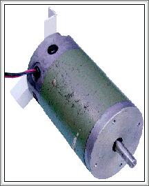
The generator I used was actually a large permanent magnet DC motor from an old vertical computer tape drive.
These are very robust, well built motors about the size of a large car starter motor. They are simple and reliable, and as generators are extremely efficient-connecting one to a torch bulb causes the bulb to be blown by a quick flick of the shaft!
The rotor slides directly onto the end of the motor shaft, and is held in place with a stainless steel bolt.
In this design, I decided to see if I could do away with having a top bearing. The bearings in the tape drive motor are at least as strong as the average car alternator bearing, and the local bearing shop gave me specs that indicate that most bearings this size will take a radial load (the load the wind would place on the bearing) of up to 450kg, and an axial load (the load from the rotor's weight) of up to 45kg.
This was heaps for my uses, so I decided to leave out the top bearing and see how the turbine went.
The mast
This was made from a 2200mm length of 150mm diameter PVC water pipe, just like the rotor. In sections this diameter and this length, PVC pipe is quite rigid.
The pipe was buried about 400mm into a hole and concreted into place.
The mast does still flex a bit in a strong wind and if this proves to be a problem it can easily be made rigid by filling with concrete.
The generator is mounted to the top of the pole by means of a stormwater pipe endcap.
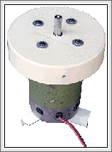
The DC motor fitted to the plastic end cap which holds it to the mast
The face of the generator has four screw holes, so it was just a matter of drilling corresponding holes into the end cap, and one much larger hole in the centre for the shaft. Front view of the motor note the threaded holes in the face plate
This rear view shows the three plastic angle sections used to make the motor a tight fit in the mast
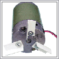
By itself, this would not have been strong enough, as the end cap would have flexed and eventually broken through, so I attached three short braces made from 25 x 25 x 3 plastic angle to the other end of the generator.
These were fixed to the motor using machine screws into the bottom end plate, and point out away from the centre of the generator. The overall diameter of the circle they make is the same as that of the inside of the pipe, so that when the generator is slid into the pipe the whole assembly is quite solid.
Hopefully this will be all that is required, but I suspect that the end cap may still not be quite strong enough, so I might have to replace it with a metal equivalent further down the track.
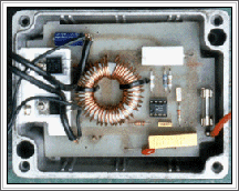
The step up converter built from a kit. It starts from just four volts snd outputs s regulated 14 volts to the battery
Voltage matching
The output voltage of the generator is actually quite low at the speeds it is likely to turn at attached to a Savonius rotor. At 200 RPM the output is only about four or five volts.
While this is obviously not enough to charge a 12 volt battery by itself, a bit of clever circuitry solved the problem.
Some time back a circuit was published in one of the electronics magazines that allowed a 12 volt battery to be charged from another.
This was used for charging small sealed-lead acid batteries from a car battery, and involved a switchmode step-up circuit to provide a regulated 13.8 volts or so from 12 volts from the car battery.
I have built several of these from various suppliers, and they work quite well.
The one I used I already had from another disused project, so I tested it and found that it would output the required 13.8 volts from as little as four volts in.
This kit was originally bought from Jaycar Electronics, who no longer sell it, but they do have a pre-built module called a solar power converter, cat# AA0259, that will take an input voltage from one to ten volts and charge a 12 volt battery-perfect for uses such as this.
The unit seemed ideal for my turbine so I connected it to the generator and tested it. At under 200 RPM I was getting full charging voltage, with available current increasing as rotor speed increased.
Final assembly
The circuit was housed in a box and slid down inside the tube before the generator and end cap were fitted. The cables from the output of the circuit run down inside the mast and out of a sealed hole at the bottom, through some flexible conduit to the box containing the gate opener circuitry.
The mast and turbine were both painted green to help them blend in with their surroundings. The photos show the turbine before its paint job.
To prevent water getting into the generator bearing, a skirt will be attached around the perimeter of the bottom of the turbine.
Costs
The turbine was very cheap to build, the most expensive part being the second hand tape drive motor which cost $25. The voltage conversion kit cost $24 a couple of years back, and the rest of the material was free.
The water pipe was salvaged second-hand from a building site, while the aluminium sheet was from some old signs I found in my workshop after we moved in.
The only other expenses were a dollar or two worth of paint and rivets and $5 for a bag of concrete.