In the first part (Ref. 1) of this Design Idea (DI), we saw how to use the TDA7052A (or similar) power amp to build a minimalist siren-type power oscillator, and also, having looked at that device’s distortion characteristics under various operating conditions, a simple but half-decent Wien bridge oscillator. In this second part, we’ll turn that semi-decency into something even more respectable, concentrating on minimizing distortion and ignoring the siren song of raw power. We will also stick with a 5-V supply, even though the chip can handle up to 18 V. Figure 1 shows the new circuit.
 |
|
| Figure 1. | Adding more precise level-sensing allows much better amplitude control and also reduces distortion. |
Most of the changes are in the control loop, but input resistor R5 has been increased because we have more gain available now that Vcon can be driven high as well as just being pulled low. In passing, the series combination of R5 and U1’s nominally 20k input resistance shunts R2/R4 a little; a slightly disturbing operation. Adding 120k across R1/R3 could compensate for that, but the practical difference is tiny. The gangs on twin pots never quite match anyway, so using the lower-value half for R1 is good enough.
The control loop, detailed
Peak output levels are now sensed by comparison with the reference voltage defined by R9 (or its wiper) and R10. (Be careful: pot R9 and fixed resistor R10 should match, so the latter may need to be trimmed.) The junction of R11 and R12 floats at ~650 mV until the peak amplitude exceeds the reference, when D1 or D2 will briefly pull it lower by ~450 mV. The resulting attenuated pulse stream is filtered by R6/C6 and R7/C7 and level-shifted and buffered by Q1 into U1’s Vcon pin. That attenuation is necessary because the effective control-loop gain would otherwise be excessive. U2 is an MCP6022, which has a low input-offset voltage and is fast enough to work well as a comparator. The overall temperature stability is good, the output level scarcely changing between 20 °C and ~50 °C.
Any residual ripple in a control loop like this will cause distortion by modulating the signal. It’s minimized by the lead-lag filter R6/C6 and C7/R7, which also controls the settling time. The values used leave the loop somewhat under-damped at low frequencies, but are a good compromise.
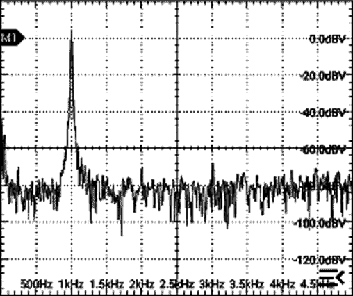
The spectra with unloaded outputs at 0 dBV and –10 dBV are both shown in Figure 2.
 |
|
| Figure 2. | The spectra for 1 kHz outputs at 0 dBV and –10 dBV, showing THDs of around –60 and –73 dB respectively – say 0.1% and 0.02%. |
Further reducing the output levels doesn’t improve distortion much, partly because this control scheme then becomes less stable. Any offset of one output relative to the other can result in one “phase” of pulses being missed, leading to increased second-harmonic distortion, as implied by the relative levels of second and third harmonics for the two levels shown in Figure 2. Trimming the power amp’s offset makes surprisingly little difference, so it isn’t implemented.
Trying to derive the control voltage from a more complex full-wave rectifier gave virtually the same distortion figures, so we’ll stick to Figure 1’s circuit, run it at –10 dBV or a little less, and accept its THD.
Some finishing touches
Swapping the capacitors C1 and C2 for 3n3 and 330n parts gave the expected performance on higher and lower ranges, though distortion was a few dB higher on the low range, and the level was less well-controlled at the highest frequencies. All that’s needed to turn this into a useful kit is an output stage, for which the fairly conventional circuit of Figure 3 works well.
 |
|
| Figure 3. | A simple output stage can deliver up to about +5 dBV, which is the rail-to-rail swing for a 5 V supply. |
The extra stage adds almost no distortion, and leaves a spare op-amp (U3b) which could be used to invert the signal from U3a to provide antiphase outputs. One final spectrum, taken with the oscillator set for –10 dBV and the output for a swing of nearly 5 V, is in Figure 4. That confirms an overall THD of –73 dB, or 0.022%. Hardly earth-shattering, but still quite decent.
 |
|
| Figure 4. | The spectrum at the output of Figure 3 for an output of ~+5 dBV. |
No tweeters were harmed in the making of this DI, though a 10-Ω, ¼-W load resistor started to smoke. A 1-W part would have been healthier, as it would only have vaped.
Reference
- Cornford, Nick. "Power amplifiers that oscillate – deliberately. Part 1: A simple start."