This easy-to-build PWM source is a handy testing tool for hobbyists, technicians, engineers and other RC-based device developers.
I work at a university where I’m charged with designing and developing all manner of circuits and systems for students, faculty, researchers, and the like. These circuits include a diversity of projects relying on the standard remote control (RC) pulse-width modulation (PWM) signal for their operation.
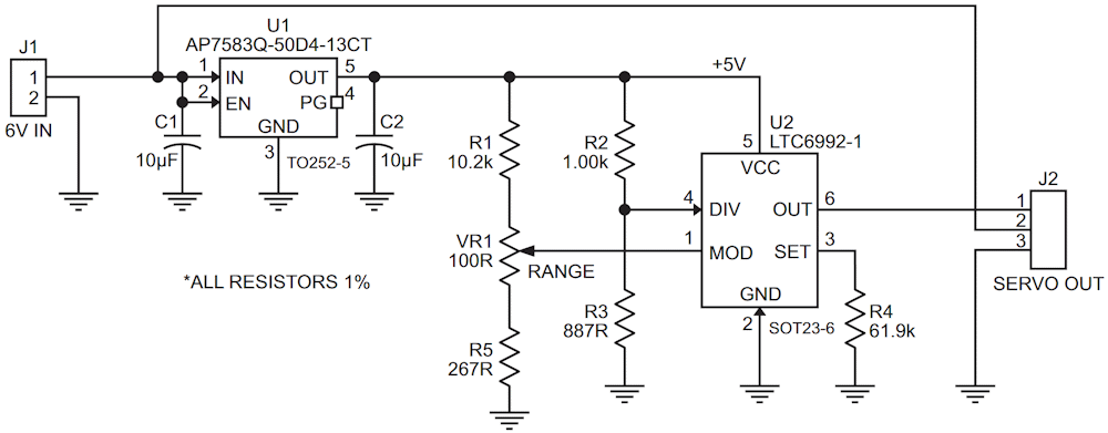
This signal is generally defined as a TTL pulse train having a frequency of 50 Hz and a width ranging from 1 ms to 2 ms. While these parameters can be programmed into most waveform generators, alternatively having a small, dedicated-function gizmo at the ready can prove to be really convenient! Figure 1 shows what I came up with.
 |
|
| Figure 1. | The standard RC PWM signal used to control a myriad of devices is usually obtained using transmitters and receivers. This alternative RC servo operator circuit implements a convenient alternative jig that simplifies attaining various testing objectives. |
Components C1, U1, and C2 comprise a low dropout 5 V regulator. More generally, any 5 V regulator IC can be employed, so long as the dropout is under a volt. Typically, RC servos run on 6 V, though some will run on as many as 8 V. The nominal input, indicated as 6 V here, is forwarded to the servo output for convenient experimentation as shown.
he PWM source is based on Analog Devices’ nice-and-simple LTC6992-1. The trick is selecting the right resistor values, which are shown in Figure 1. Rather than generate a PCB, I soldered up the circuit using proto-board, through-hole components, and adapter boards for both ICs. If done on a PCB using surface-mount components, the entire circuit will take up only about 1 in2.
I don’t personally keep an RC transmitter and receiver combo in my lab. Even if I did, I’d need someone to manipulate the controls while I measured the values of interest on the system I’m developing. With this handy alternative circuit, I can run all my tests without human assistance, not to mention without the RC hardware. It has proven useful on numerous occasions.
Figure 1, The standard RC PWM signal used to control a myriad of devices is usually obtained using transmitters and receivers. This alternative RC servo operator circuit implements a convenient alternative jig that simplifies attaining various testing objectives.