There are times when you would like to control a DC motor using a simple +5 V logic swing signal. The circuit below performs this feat and also includes an automatic motor braking circuit.
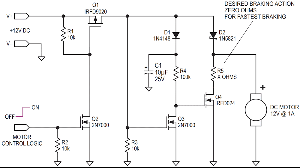
When the input logic signal swings from 0 V to +5 V, the n-channel MOSFET Q2 turns on, which turns on the p-channel MOSFET Q1. Current flows into the motor through the schottky diode D2. When the control logic swings back 0 V, Q1 turns off. This activates the braking action of Q4, which applies a short across the motor. The sudden stop is often desired in some motor controlled systems.