Software description:
The software is written in ‘C’ language and compiled using CodeVision AVR ‘C’ compiler. The source program is converted into hex code by the compiler. Burn this hex code into ATmega16 AVR microcontroller.
The source program is well commented and easy to understand. First include the register name defined specifically for ATmega16 and also declare the variable. Set port A as the input and port D as the output. The program will run forever by using ‘while’ loop. Under ‘while’ loop, read port A and test the received input using ‘switch’ statement. The corresponding data will output at port D after testing of the received data.
Working:
In order to control the robot, you need to make a call to the cell phone attached to the robot (through head phone) from any phone, which sends DTMF tunes on pressing the numeric buttons. The cell phone in the robot is kept in ‘auto answer’ mode. (If the mobile does not have the auto answering facility, receive the call by ‘OK’ key on the rover-connected mobile and then made it in hands-free mode.) So after a ring, the cellphone accepts the call.
Now you may press any button on your mobile to perform actions as listed in Table III. The DTMF tones thus produced are received by the cellphone in the robot. These tones are fed to the circuit by the headset of the cellphone. The MT8870 decodes the received tone and sends the equivalent binary number to the microcontroller. According to the program in the microcontroller, the robot starts moving.
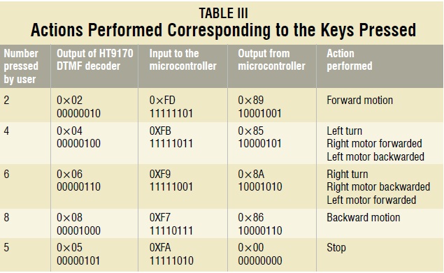
When you press key ‘2’ (binary equivalent 00000010) on your mobile phone, the microcontroller outputs ‘10001001’ binary equivalent. Port pins PD0, PD3 and PD7 are high. The high output at PD7 of the microcontroller drives the motor driver (L293D). Port pins PD0 and PD3 drive motors M1 and M2 in forward direction (as per Table III). Similarly, motors M1 and M2 move for left turn, right turn, backward motion and stop condition as per Table III.
Construction:
When constructing any robot, one major mechanical constraint is the number of motors being used. You can have either a two-wheel drive or a four-wheel drive. Though four-wheel drive is more complex than two-wheel drive, it provides more torque and good control. Two-wheel drive, on the other hand, is very easy to construct.
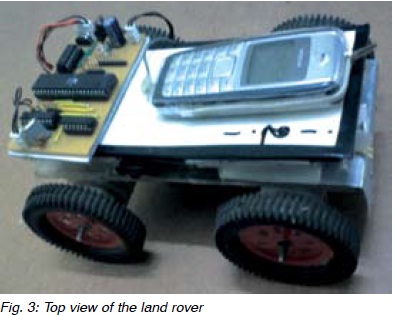
Top view of a four-wheel-driven land rover is shown in Fig. 3. The chassis used in this model is a 10×18cm2 sheet made up of parax. Motors are fixed to the bottom of this sheet and the circuit is affixed firmly on top of the sheet. A cellphone is also mounted on the sheet as shown in the picture.
In the four-wheel drive system, the two motors on a side are controlled in parallel. So a single L293D driver IC can drive the rover. For this robot, beads affixed with glue act as support wheels.