On my desktop PC I have a speakers and a headphones. Usually I use headphones, but when I need to switch to speakers I need to physically plug in speakers instead of headphones to my PC’s soundcard. I wanted to solve this problem for a long time, but never get around of that until recently I saw "Simple LAN Controlled Stereo Audio Switch" post on Hackaday.
And so I’ve decided to build my own really simple audio multiplexer.
Features
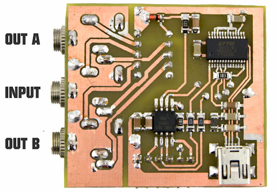
- 1 Input, 2 Outputs (or the other way around)
- Built upon FT232R (has drivers for Windows, MacOS and Linux)
- Easy to control from any serial terminal program
- Consumes only about 15mA
- Completely isolated analog ground
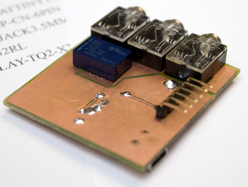
- Standard 3.5mm audio connectors
So, basically it’s a low-power USB-controlled relay which used to switch audio signals. When you connect it to the PC, OS detects it like a virtual serial port (COMx in Windows, /dev/ttyUSBx in Linux). Then you can use any serial terminal program to connect to that virtual serial port and control it using three single-character commands.
Here I’ve used Terminal v1.9b – free serial terminal for windows to control my audio mux.
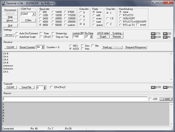
The supported commands are:
- a – switch to channel A
- b – switch to channel B
- t – toggle between channels
As you can see after each command it responds with channel that currently active. For example, if you would send “b” command, it will respond with “CH B” after channel is switched to B. If it will recieve any other command then those three, it will respond with “Unknown”.
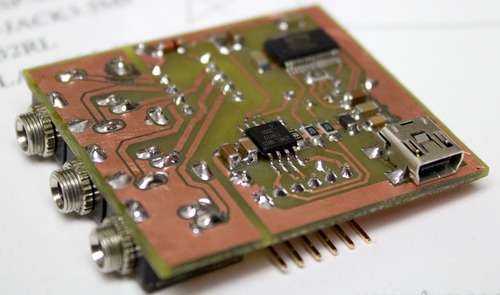
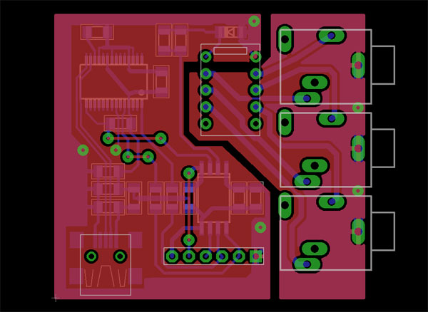
Design
As you can see, the “audio” ground completely isolated from “digital” ground. And I’m using top copper layer as a shield for both, audio and digital ground. This helps to isolate audio part from picking up noise from digital circuitry and other EMI.
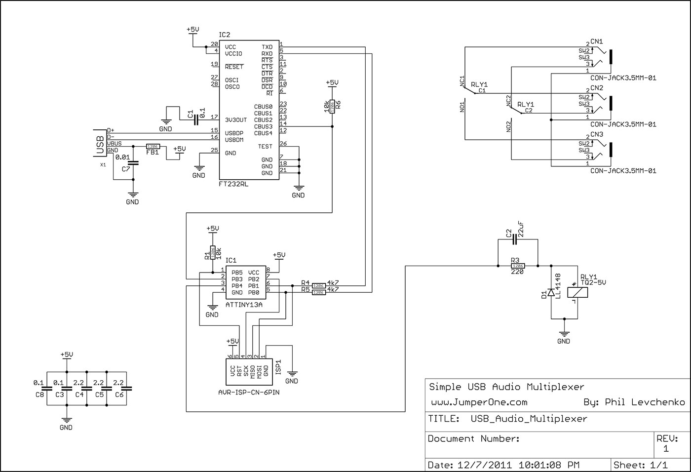
The schematic of this USB Audio Multiplexer is pretty straight-forward.
USB<—>FT232R<—>ATtiny13A<—>Relay
So, I just will point out some design aspects of it.
Relay connected not straight to MCU pin, but it is connected through R3 and C2. It’s made for lowering relay power consumption from 28mA to about 12mA. I wrote about this trick in my article: Using Relays (Tips & Tricks). This might be helpful when this device is connected through usb-hub full of devices, when even ~15mA can make a difference. But it is not necessary implement this.
Pin PB3 of MCU connected to CBUS3 pin of FT232R with 10k pull-up resistor, which can be used for power saving functions, or it can be used for providing clock to ATmega13A. You can change functions of CBUS pins of FT232R using FT_Prog software which you can download from FTDI website. Ferrite bead FB1 after USB port is needed to reduce EMI noise that comes from FT232R. You can read more about this in FT232R datasheet.
If you can’t find the exact relay I’ve used in this design, you can use any DPDT (2 Form C) 5VDC signal relay which not exeeds ATtiny13 maximum pin current.
And for different relay you might need to change R3 and C2 values (if you don’t care about saving a couple of dozen of milliamps, just put jumper in there).
MCU Choice and Firmware
For this simple task I was looking for cheap microcontoller(preferably from Atmel of Microchip) with minimal number of pins and with hardware UART. But the smallest and cheapest thing I found was the PIC16F688T from Microchip.
Well, I guess 14 pins is too much for this task, so I’ve ended up using Atmel ATtiny13A, which, btw I had in my junk box. I just decided to write software UART for this micro. To do that I’ve used AVR304 app-note from Atmel “Half Duplex Interrupt Driven Software UART”. I’ve used 8-bit timer and one external interrupt to do that, but for this simple task it’s actually is overkill. It is possible to use only a small fraction of memory to implement software UART without using external interrupts and timers. Anyways, if you want you can still do that.
Before flashing the firmware as-is, you need to change fuses to get 4.8MHz internal oscillator frequency.
Issues
The only issue I had with this device was ATtiny13 internal RC oscillator calibration. UART protocol is very sensitive to changes in oscillator frequency. ATtiny13 internal oscillator is calibrated under 3V and 25 degrees C, but in this Audio Multiplexer it’s powered straight from USB port 5V, and because of that it can even not work after you will flash the firmware. You might need to tweak number of timer cycles in firmware (read comments in code, there’s only two values at the beginning of the program).
To conquer that you might try to configure CBUS3 pin of FT232R as a clock source for ATtiny13, hoping that FT232R internal RC oscillator is more precise than ATtiny’s oscillator. Or put external crystal for FT232R and still use CBUS3 as ATtiny13 clock source – that would’ve been the ideal solution. I maybe will compare FT232R internal oscillator frequency stability against ATtiny13A internal oscillator. Maybe. If you’ll try to do that before me, it would be interesting to know what the result is.
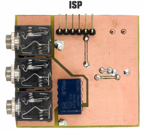
At first I wanted to make single-sided board, but eventually I’ve end up with double-sided one. Because of that the USB connector stayed on the bottom of the board and audio connectors on the top. But if you want you can easily change that fact.
Downloads
Eagle CAD Files + BOM (.zip) - download
ATtiny13A Firmware (Sources + HEX files) (.zip) - download
