Part 1 - Theory
In the first part of this discussion, the features of ACS712 device were briefly discussed. Now we will use that theory to implement the ACS712 sensor to make a simple DC current meter. The analog output voltage from the sensor is measured through an ADC channel of the PIC16F1847 microcontroller. A voltage to current conversion equation will be derived and implemented in the firmware of the PIC microcontroller and the actual load current will be displayed on a character LCD.
|
|
|
| Measuring dc current with ACS712 sensor. |
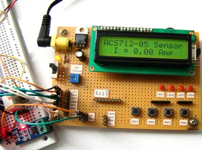
Experimental circuit setup
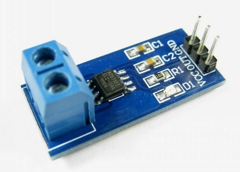
We are going to setup a test experiment to demonstrate the use of ACS712 to measure a DC current. I am using an ACS712-05B breakout module (you can find them cheap on ebay) for this purpose. It has got a 1 nF filter capacitor connected between pin 6 and ground, a 100 nF decoupling capacitor between power supply lines, and a power on LED soldered on the board. The power supply and output lines are accessible through header pins on one side, whereas, the current terminals are connected to a 2-pin terminal block on the opposite side, as shown below.
|
|
|
| ACS712-05B breakout module |
The experimental circuit diagram of the DC current meter is shown below. A 2.7 Ω (rated 2 Watt) resistor is connected in series with the current terminals and a varying dc voltage is applied to vary the current through the resistor and the current path. The output of the sensor module goes to AN0 (pin 17) ADC channel of the PIC16F1847 microcontroller. A 16×2 character LCD is used to display the measured current output.
|
|
|
| Circuit diagram. |
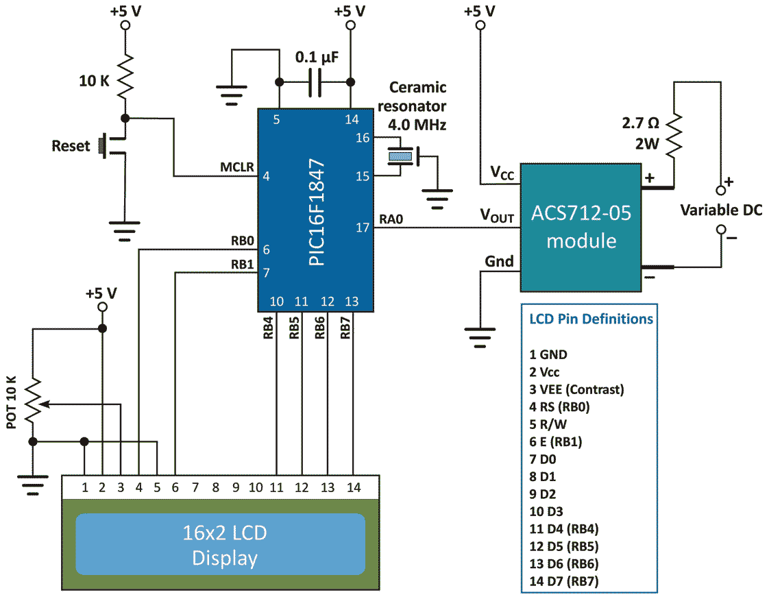
I am using my PIC16F1847 breadboard module along with the Experimenter’s I/O board to demonstrate this experiment.
The microcontroller uses the supply voltage (+5V) as reference for A/D conversion. The digitized sensor output is processed through software to convert it to the actual current value. The mathematics involved in the process is described in the white board below.
For Vcc=5V and ADC Vref=5V, the relationship between output voltage and ADC Count is

But,
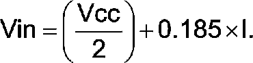
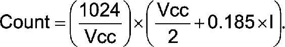
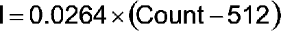
Important note: The calculations shown above considered supply voltage Vcc = Vref = 5.0 V. Interestingly, the final equation relating I and Count remains the same even the power supply fluctuates. For example, suppose Vcc fluctuates and becomes 4.0 V. Then, the sensitivity of the ACS712-05B also changes to 0.185 x 4/5 = 0.148 mV. If you repeat the above calculations with Vcc = Vref = 4.0 V and sensitivity = 0.148 mV, you will end up with the same equation for I and Count. This was possible because of the ratiometric output of the ACS712 sensor.
The equation clearly tells that the current resolution for this setup is 26.4 mA, which corresponds to count 513, one count higher than the zero current offset. Therefore, this kind of arrangement is not suitable for measuring low current. You need an external Op-Amp circuit to enhance the resolution and be able to make more sensitive current measurement. If you are interested on that, you can visit Sparkfun’s ACS712 Low Current Sensor Breakout page that provides a circuit diagram for such an arrangement.
Software
The current-Count equation described above is implemented in the firmware of PIC16F1847 to compute current from digital count. The result is finally displayed on the LCD with a precision of two decimal places. The following software is written in C and compiled with the mikroC Pro for PIC compiler from mikroElektronika.
Output
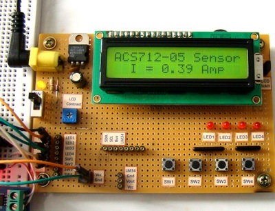
At zero input current, the ACS712 output should be ideally Vcc/2, which is equivalent to an ADC count of 512. A drift of 4.9 mV in the output voltage of ACS712 results in an offset of 1 LSB in the A/D conversion (for Vref = 5.0V, resolution of 10-bit ADC is 5V/1024 = 4.9 mV). Interestingly, one LSB is equivalent to 26mA of current for ACS712-05B. The drift of 4.9 mV or more in the zero current output voltage is considered likely to happen, which is reflected in the output shown on the LCD. I have seen the ACS712 output for zero input current fluctuating between 512 and 513 ADC counts. If it is 513, the displayed current would be 0.02 A. So it is always better to take multiple ADC measurements and then take their average.
|
|
|
|
Offset of 20 mA corresponding to 1 count. |

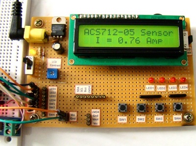
When the variable DC is set to 1.0 V, the current through the 2.7 Ω resistor should be 370 mA. The measured value is 390 mA, which is off by 1 LSB.
|
|
|
| Output for variable DC input equal to 1.0V. |
|
|
|
|
Output when DC inpt equal to 2.0 V. |
This concludes the discussion on the ACS712 current sensor. However, one concern is still not addressed. How would you measure an AC current with the ACS712 sensor? Keep in mind that the ACS712 sensor provides an instantaneous output corresponding to the current flowing through the conduction terminals. If the current flow is in positive direction (from pins 1 and 2 to pins 3 and 4), the sensitivity of the device is positive, and the ACS712 output voltage rises above Vcc/2. But if the current changes its direction, the sensitivity will be negative and the output of the ACS712 decreases below Vcc/2. This means, for an AC current, the 10-bit ADC output measured by the microcontroller oscillates about 512 counts. Therefore, the microcontroller needs to sample the sensor output fast enough so that the RMS value of the current can be computed from them.
Downloads
Source Code and Firmware - download
