Francois AUGER & Philippe Fretaud
EDN
Many previous Design Ideas [1, 2] have shown how to use the Charlieplexing technique [3] to drive as many LEDs as possible with a minimum number of I/O lines. This Design Idea shows how you can drive three LEDs and scan three switches with only three I/O lines instead of six. Using the same principle, it will also be possible to manage four switches and two LEDs, or five LEDs and one switch. It works well with Atmel ATmega microcontrollers including the Arduino, and could be of particular interest for any eight-pin devices, or when you’ve simply run out of I/O.
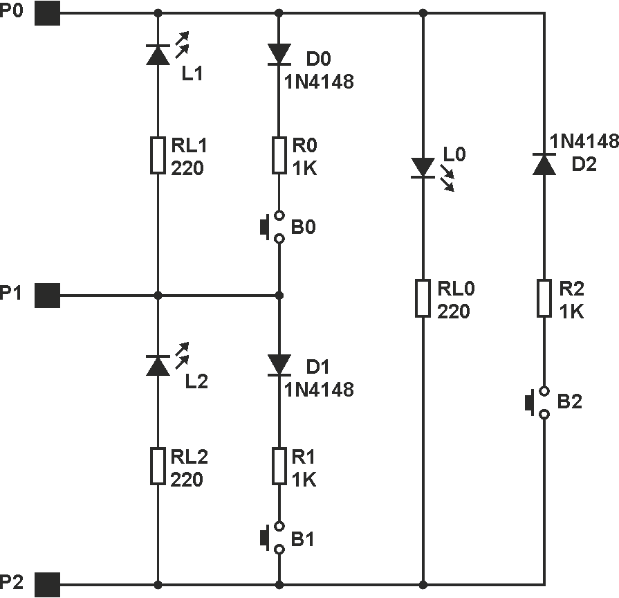
The circuit in Figure 1 shows how to do that. The three LEDs are driven on the same principle, and the three switches are managed the same way. So, we can just consider how to drive the L0 LED, and how to read the state of the B0 button. To drive LED L0, P0 and P2 must be configured as outputs. P2 is set low and P0 is set high for the LED to be turned on, or low for L0 to be off. For L0 to be the only LED on, P1 must be configured as an input. Diode D2 is used to avoid a short circuit when B2 is closed while L0 is turned on.
 |
||
| Figure 1. | ||
To scan button B0, P1 must be configured as an output and set low. P0 is configured as an input, with the optional internal 20 kΩ pull-up resistance enabled (input pins with switchable pull-up resistors are available with any ATmega microcontroller and with several other MCUs). Thanks to this pull-up resistance, P0 will be at a high level when the button is open. When the switch is closed, the voltage on P0 is approximately:
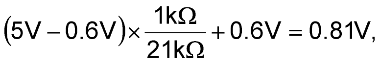
which will be considered a low logic level.
For the L0 LED to be turned off, P2 must be configured as an input (high-impedance state). The diode D0 is used to avoid a short circuit when LED L1 is turned on while B0 is closed.
Listing 1 (syntax-coloured PDF) is a small Arduino program showing how to blink the three LEDs successively, turning a LED on solidly when the corresponding button is closed (plain text below).
Of course, this design can be generalized: With four I/O lines, it will be possible to manage six LEDs and six buttons. With N lines, it is possible to manage N × (N – 1)/2 LEDs and the same number of buttons.
