Introduction
Data loss is a concern in telecom, industrial and automotive applications where embedded systems depend on a consistent supply of power. Sudden power interruptions can corrupt data during read and write operations for hard drives and flash memory. Often, embedded systems need just 10 ms to 50 ms to backup volatile data to prevent loss.
Data backup is used in embedded systems for maintenance, troubleshooting and repair work. In complex industrial metal machining equipment, it’s important to store the position and state of multiple tools after power disconnect to prevent equipment failure when power is later restored. These applications require a stable power supply and data retention, but unreliable power sources make it difficult to accomplish. Long supply lines, discharged batteries, unregulated AC adapters, load dumps and switching high power electrical motors result in widely fallible input supplies. As a result, developers of embedded systems prefer to design with the widest possible input voltage range, enabling use in a variety of applications and environments.
Circuit Description
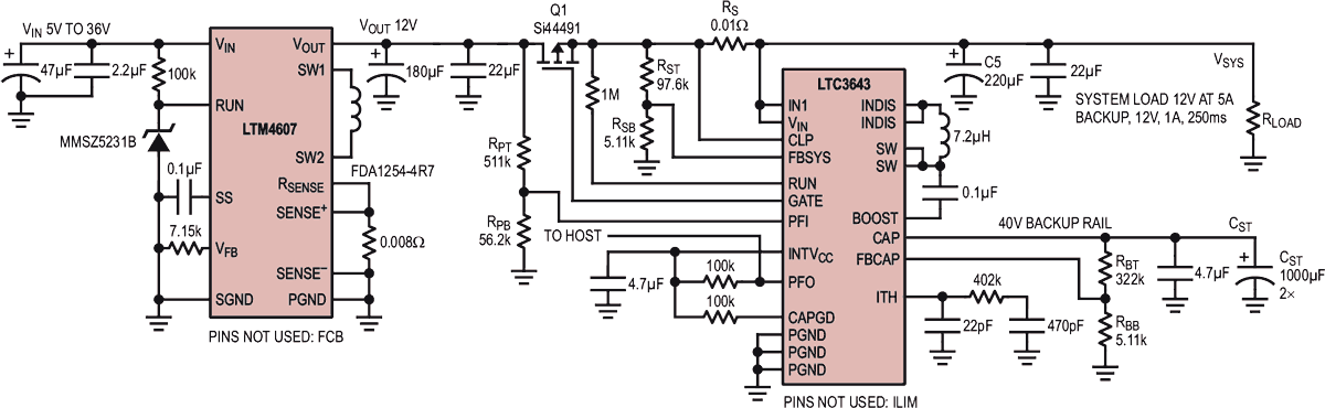
Figure 1 shows a system that delivers reliable primary power plus holdup power for data backup. This solution is centered on the LTC3643 bidirectional power backup supply. When the input voltage is present, the LTC3643 charges the storage capacitor, CST, up to 40 V in boost mode. When the input voltage is interrupted, the LTC3643 discharges the storage capacitor into the load in buck mode, keeping the nominal voltage at the load (VSYS) in the range of 3 V to 17 V.
 |
||
| Figure 1. | LTC3643 Backup Supply, Electrical Schematic. | |
The relatively high voltage of the backup storage rail increases stored energy of this solution (E = CV2/2) and enables the use of electrolytic capacitors as a backup storage component. Electrolytic capacitors are inexpensive and widely available, significantly reducing the cost of the backup solution. Another advantage of the LTC3643 is its ability to support 12 V systems, the default standard voltage rail in many automotive and industrial applications.
In Figure 1, the LTM4607 μModule® buck-boost converter acts as the front end regulator, producing 12 V at up to 5 A from a 5 V to 36 V input, such as a vehicle battery. The buck-boost regulator maintains a steady 12 V output so long as the input voltage stays within the specified range, allowing VSYS to ride through brownout and overvoltage conditions such as automotive cold crank and load dump. When the input voltage is interrupted or moves out of this range, the LTC3643 based backup power solution maintains the VSYS system voltage to allow for short-term data backup.
Circuit Functionality
In normal operation, when the P-channel MOSFET Q1 is on, the flag PFO is low and the electrolytic capacitor array CST is charged to 40 V. When the input voltage is interrupted, the LTC3643 turns Q1 off, sets the flag PFO high and starts to discharge the CST capacitor array, maintaining 12 V to the load. When Q1 is in the off state, the body diode of this transistor effectively isolates the load from the input lines. The PFO flag identifies the fault and signals the host computer to disconnect the noncritical loads and supply circuitry. Here it is assumed that the critical circuitry related to data retention consumes 1 A for up to 100 ms.
 |
||
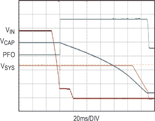
| Figure 2. | LTC3643 Backup Supply, Electrical Schematic. | |
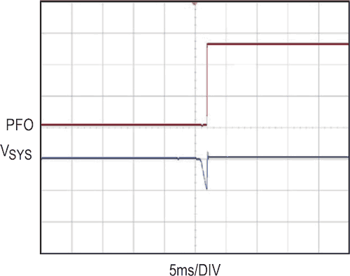
Figure 2 illustrates the entire switchover process. At the start, the system load is supplied by the LTM4607, as the input voltage is present. When the input voltage is interrupted, the LTC3643 supports the system load by discharging the storage capacitor. Figure 3 shows the timing of the switchover in more detail. The load voltage falls to 10 V, a value set by the resistor divider RPT/RPB and then recovers to the nominal 12 V, set by the resistor divider RBT/RBB.
 |
||
| Figure 3. | Detailed View of Switching Waveforms (PFO 1V/DIV, VSYS 2V/DIV). | |
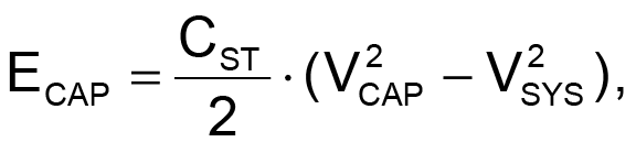
The formulas for an estimation of the required storage capacitance and holdup time are below. If a more detailed analysis is needed, the necessary information can be found in vendor’s documentation.
- Energy Stored
- Energy Needed to Supply Load for Time TH

- Holdup Time
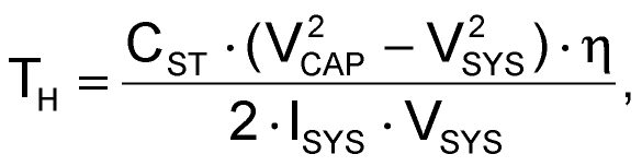
η = efficiency
- Storage Capacitance
Conclusion
The LTC3643 is a highly integrated, high performance backup regulator. The design shown in this Design Note combines the advantages of this IC with a high efficiency buck-boost LTM4607 μModule regulator. Together, these devices enable a small footprint, efficient and cost effective solution for data retention and backup in automotive and industrial applications.
