Massimo Gottardi
EDN
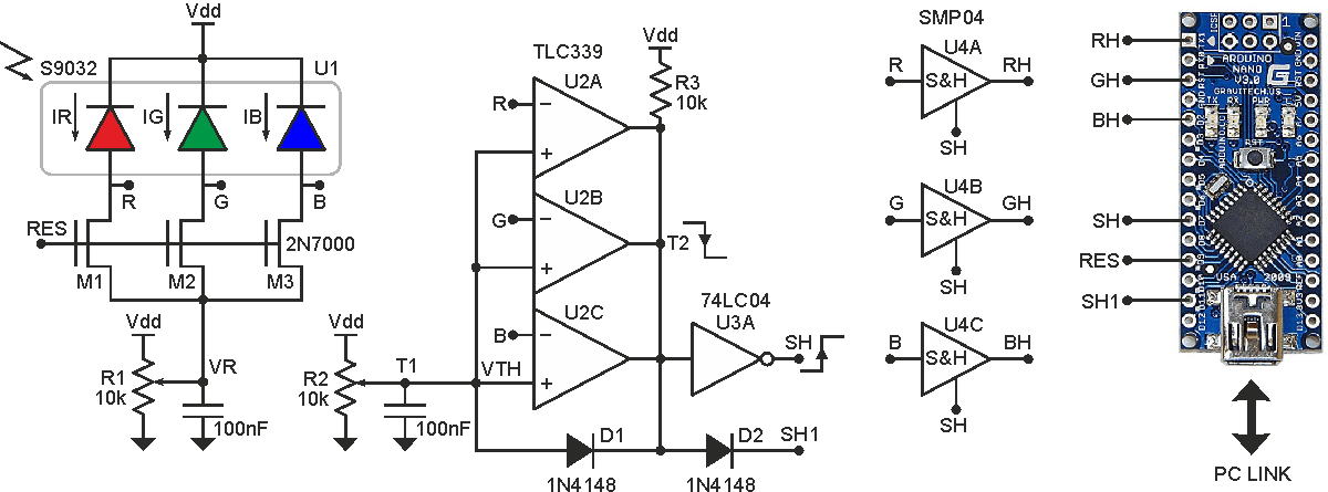
The Design Idea in Figure 1 is a color detector capable of generating an RGB triplet over a high dynamic range, a useful attribute for machine vision applications. The circuit implements auto-exposure control to achieve this. Thus, RGB values for a subject are invariant over a range of light intensity.
 |
||
| Figure 1. | RGB sensor with auto-exposure control. | |
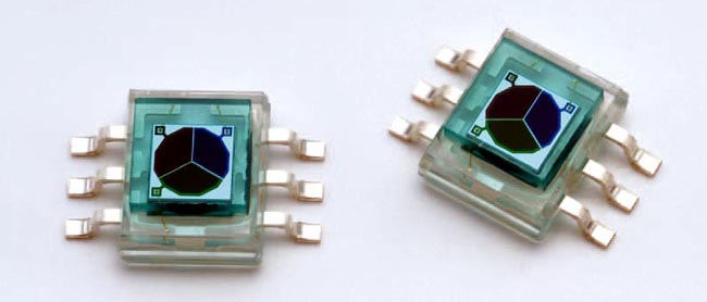
The three common-cathode RGB photodiodes (U1, Figure 2) are reverse-biased and pre-charged to VR (typically 0.5 V) through the three N-channel MOSFETs (M1, M2, M3) when RES is driven high by the µC (microcontroller). After the reset phase, the voltages on nodes R, G, and B start increasing, linearly proportional to the intensity of each color component. These signals feed three comparators (U2) with wired-OR-connected outputs. The first signal reaching the threshold VTH (typically 2.6 V) causes SH to assert through inverter U3A, which strobes the sample-and-hold amplifiers, U4.
 |
||
| Figure 2. | ||
The held voltages RH, GH, and BH are then converted by the Arduino Nano for further processing. Analog-to-digital conversion could be accomplished by the µC without U4, but the successive conversions would introduce a sampling error among signals. This error is larger for brighter signals because of the higher slew‑rate. Alternatively, a µC with at least three ADCs could be used.
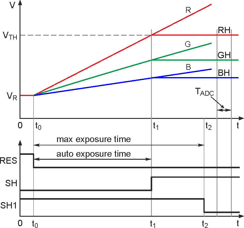
D1 adds brute-force hysteresis to the comparators, and D2 allows the Arduino to define a maximum exposure time by pulling node T2 down, holding the RGB signals. This function is necessary to guarantee a fixed operating rate of the sensor. Figure 3 shows signal timing. At time t1, when R = VTH, comparator U2A pulls low, holding the triplet [RH, GH, BH], to be converted by the µC at the end of the process (TADC). At t2 – the end of the maximum exposure time – the µC sets SH1 low and converts the inputs.
 |
||
| Figure 3. | Timing diagram. | |
Summarizing, the brightest signal among R, G, and B determines the exposure time (t1) so that no saturation occurs on any of the signals. This signal compression enables a dynamic range of about 100 dB using an 8-bit ADC. Moreover, to reach such performance, it is not necessary to tune any circuit parameter.
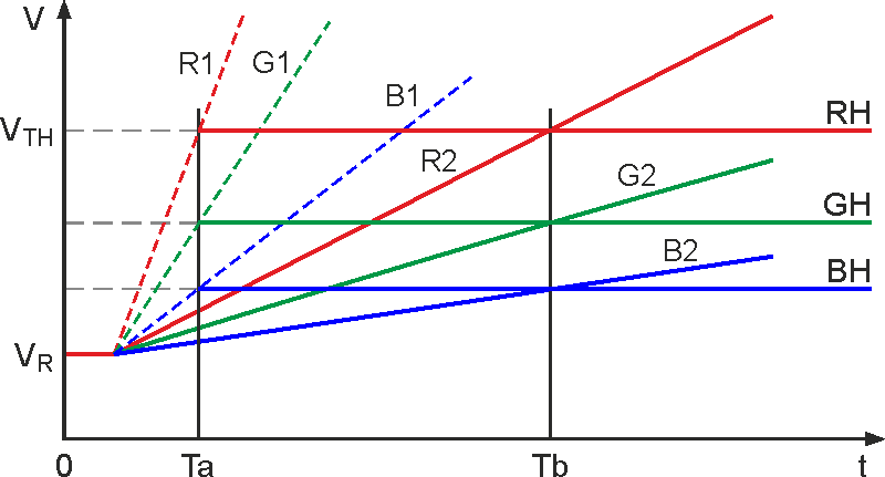
Figure 4 explains how high dynamic range is obtained through the auto-exposure control. Given a target, for each light intensity, there will be always an exposure time which guarantees the triplet [RH, GH, BH] to be constant:
 |
||
| Figure 4. | An example of two RGB triplets referred to the same target acquired at two different light intensities. [R1,G1,B1] are bright signals, sampled at Ta, while [R2,G2,B2] are dark signals, sampled at Tb. Since [R1,G1,B1]Ta = [R2,G2,B2]Tb, the chromaticity of the object does not depend on the light intensity. |
|
Although fully integrated, digitally-interfaced RGB sensors are available (e.g., Avago APDS-9950, ams TMG3993), they do not implement auto-exposure, and hence may require multiple exposures and µC intervention to achieve such functionality.
