Wayne Sward
EDN
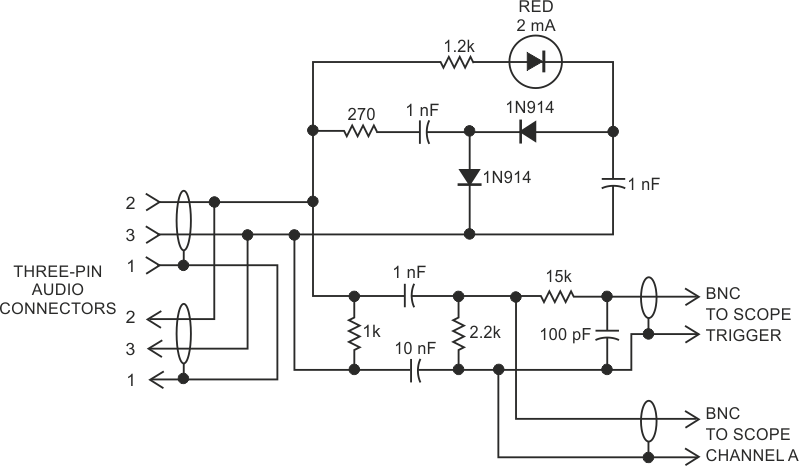
The circuit in Figure 1 efficiently monitors common digital-audio signals. One format for such signals is the Audio Engineering Society (AES) 44.1- or 48-kHz standard. Typically, the data consists of a serial data stream with a data rate of approximately 1 Mbps. A lower frequency pulse interspersed in the data stream synchronizes data frames every 16 to 20 data bits. The amplitude of the data and sync pulses is 3 to 12 V p-p, with one cycle of an ac wave representing each bit. The signals are on a two-wire cable that you can isolate from ground by using signal transformers or capacitors. Several other data-transmission standards use a similar data format. An oscilloscope does not reliably trigger on such a waveform; thus, troubleshooting and signal tracing such systems is difficult.
The circuit in Figure 1 is passive and small and uses no power supplies. You can keep it in a toolbox, ready for instant use. The two diodes and associated capacitors form a voltage doubler to provide a bias voltage of approximately –2 to –10 V. The 2-mA LED connects between one of the signal lines and this bias voltage. Whenever the signal-line voltage exceeds approximately 1.5 V, the LED turns on. At a data rate of nearly 1 MHz, the LED appears to continuously glow when good data is present. The LED's intensity is proportional to the peak-to-peak voltage level, so you can easily observe low or high voltage levels. Intermittent levels, crosstalk, or interference on the signal causes the LED to flicker. The LED circuit is differential and measures the voltage levels between the two signal lines. Common-mode ground noise or hum do not affect the LED's display. The voltage doubler is an efficient way to increase the sensitivity of the LED without an additional power supply.
 |
||
| Figure 1. | A passive circuit gives a good indication of data activity on digital-audio lines. | |
The two coupling capacitors sample the high-frequency data waveform but reject any low-frequency common-mode noise or hum. You can display the data waveform on an oscilloscope to more closely inspect the wave shape. The 15 kΩ resistor and 100 pF capacitor form a simple but effective filter to detect the sync bit in the data stream. You feed this sync bit to the external sync input of the oscilloscope, resulting in a stable display of the data frame. The coupling capacitors avoid creating a ground loop between the signal lines and the grounded, shielded input of the oscilloscope. You can readily monitor data amplitude, waveshape, and activity of individual bits with the oscilloscope.
