Samuel Kerem
Electronic Design
The filter described below is useful for detecting a signal that’s closely surrounded by spurs, even when the task is complicated by the frequency of the signal of interest wandering by a few percent. For example, in telecom, a pilot signal can originate from sources scattered around the world. Assume a 10.0-kHz signal of choice. Due to variations in oscillators, temperature conditions, and aging, a frequency deviation of ±200 Hz can be expected.
Complicate the situation with a spur at 11.0 kHz. To reject the 11.0-kHz spur, you need a filter with very sharp rolloff, but to accommodate the wandering 10.0-kHz signal, the passband of the filter should be flat from 9.8 kHz to 10.2 kHz. You can jump to the conclusion that you need a DSP-based digital filter. But don’t.
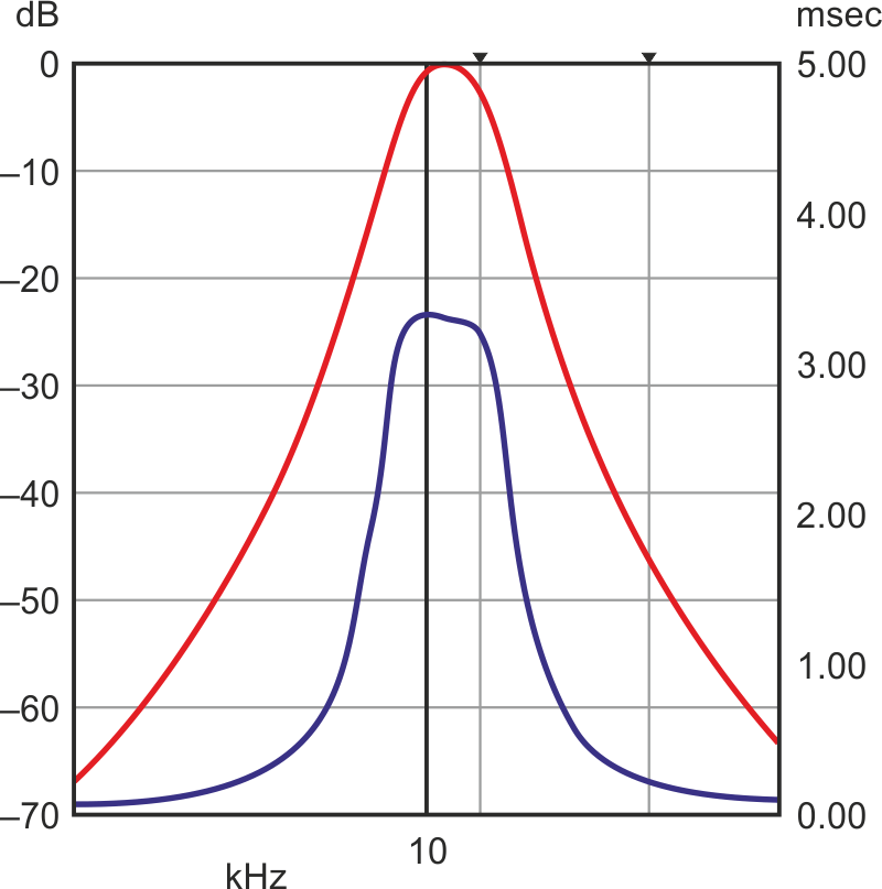
A switched-capacitor bandpass filter like the LTC1068 from Linear Technology can create the very sharp rolloff from 9.0 kHz to 11.0 kHz (Fig. 1). The two markers show attenuation of 2.9 dB at 10.1 kHz and 46.7 dB at 10.6 kHz. But the pass section is very narrow at about ±100 Hz at 3 dB.
 |
||
| Figure 1. | A bandpass Bessel 10-kHz eighth-order filter created using a switched-capacitor circuit provides the required sharp rolloff, but the passband is too narrow for a typical application. |
|
The filter center is 50 times the center-frequency clock and, according to the datasheet, can differ by ±0.9% from the calculated value. If we allow the filter pass area to scan the region of 9.7 kHz to 10.3 kHz, the worst conditions (90 Hz of the filter uncertainty and 200 Hz of signal variation) will be covered. The 11.0-kHz spur is still attenuated by over 50 dB. One caveat: a detection delay of few milliseconds will occur (Fig. 1, again).
 |
||
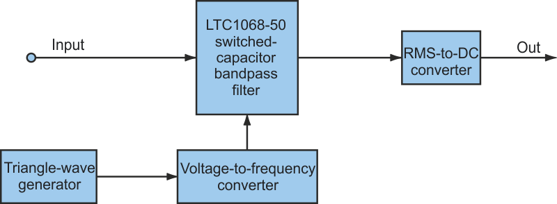
| Figure 2. | The filter’s passband can be flattened by adding a triangle-wave generator that feeds a voltage-to-frequency converter, which moves the filter’s center frequency back and forth. |
|
An improved filter design includes a triangle-wave generator that produces a voltage of “V_filter_center” ±5% (Fig. 2). This voltage is applied to the input of the voltage-to-frequency converter (VFC), which in turn moves the center frequency of the very narrow bandpass filter back and forth. The filter’s sharp rolloff creates almost vertical attenuation.
 |
||
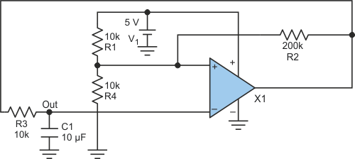
| Figure 3. | This particular triangle-wave generator outputs a voltage of 2.500 V ±0.125 V. | |
Figure 3 shows one version of a triangle-wave generator. This generator outputs 2.500 V ±0.125 V. The voltage must match the VFC coefficient to the desired frequency (for the LTC1068-50, 2.5 V produces 500 kHz). Then the filter will pass any signal of 10.0 kHz ±500 Hz to the rms-to-dc converter, greatly attenuating any frequency outside that range. For this particular design, the error budget is determined by the accuracy of the resistors and the power source.
