1. History
Back in 2000 I built one small embedded device used for repairing of broken PC monitors. The motivation was to avoid the need of one operational PC near the technician desk used only to generate test rasters, because PCs are usually ocupying lot of space and are hard to operate if one doesn't see the image (broken monitor). You can add also the operations needed to switch the resolutions in regular operating systems and you have a complete picture of using such an equipment to repair PC monitors.
Looking for an embedded solution (small size advantages) I started to look at the existing graphics chips existing on the market, but I quickly abandoned this direction because of the increased complexity for such a task. Second ideea was to use an existing general purpose microcontroller to generate video signals so I started to play with one AVR microcontroller. The chip used was an AT90S1200 which was the first AVR family member, having serious resources constraints not existing in modern present chips. After some experiments on this platform I succeded to create an embedded monitor tester aproximately the size of an portable CD player.
2. Monitor tester - second edition :)
Currently I have redesigned the old device using a new AVR chip (ATTiny2313) having improved several aspects like new resolutions, reduced dimensions, battery powered operation.
3. Feature list:
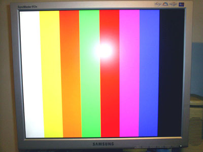
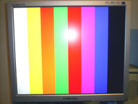
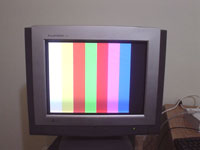
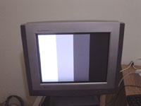
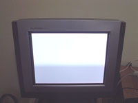
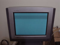
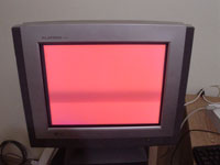
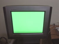
- 8 different raster images
- 4 resolutions available for each image combination: 640x480x60Hz, 800x600x60Hz, 1024x768x60Hz,1280x1024x60Hz New
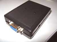
- Small size (almost credit card size)
- Portable: battery powered operation (regular 9V-6F22 type)
- DC power adapter operation: 7.5V..12V
- "Designed to box": fits perfectly into a low cost plastic box
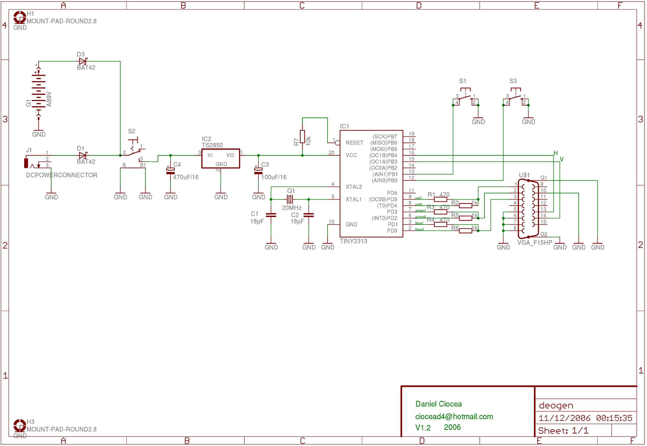
4. Schematics
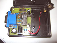
The core of the design is one ATTiny2313 microcontroller from Atmel, having the advantage of increased speed (20MHz) and several instruction set improvements (especially single clock port toggle instruction) over the previous versions (AT90S2313). Synchro H and Synchro V signals are driven directly from uC ports, R,G,B signals are converted to analog (0..0.7V) signals using simple D/A converter (resistor network).
Power supply is made using one xx2950 device chosen because its low quiscent current, important factor for battery powered devices. You can use an 78L05 equivalent integrated circuit if you are not interested in consumption optimization. Battery or DC main supply power adapter are connected using two protection diodes to prevent battery being accidentally charged. The chosen type is Schottky to minimize the direct voltage dropout (mainly for battery circuit).
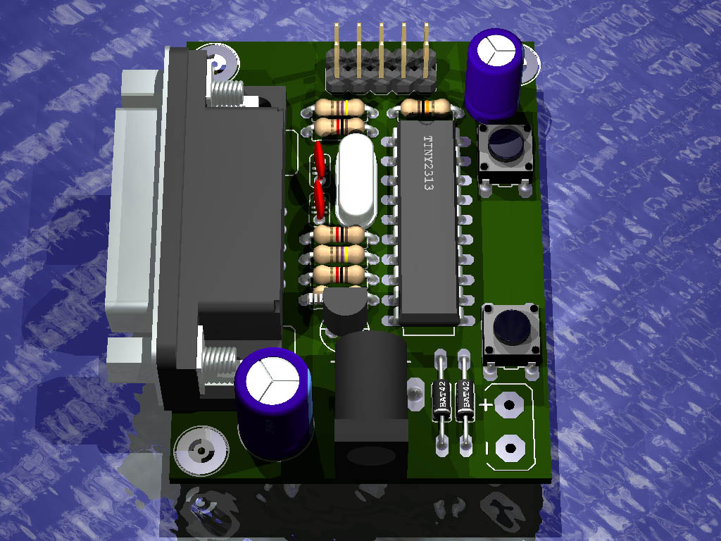
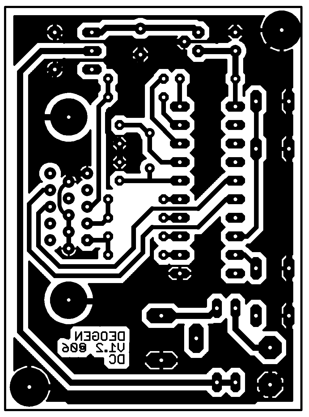
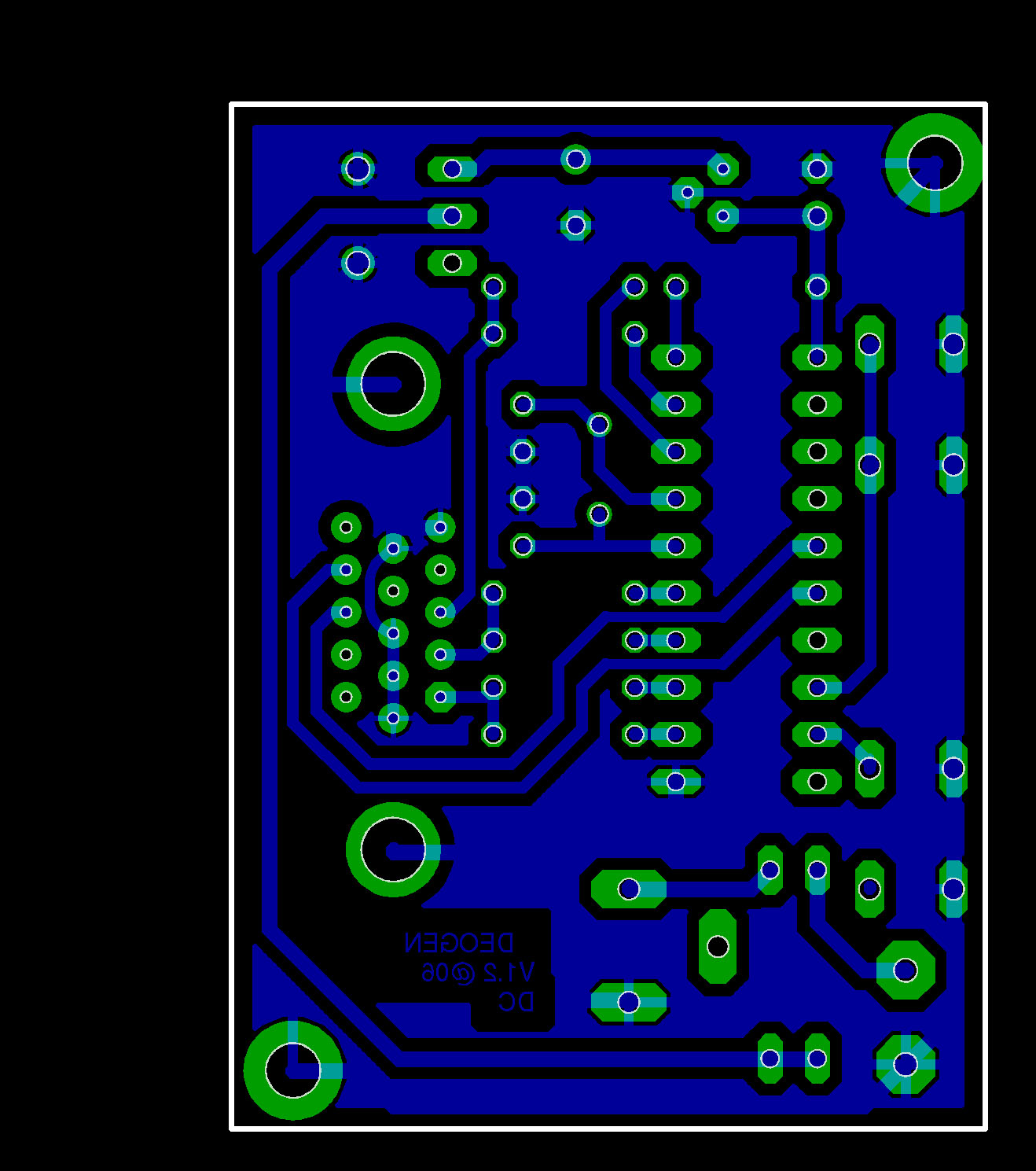
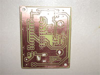
5. PCB
The main design criterias for PCB were single side routing and phisycal reduced dimensions.
click, for enlarge
click, for enlarge
click, for enlarge
Because the PCB is single side routed, it can be easily reproduced using hobby methods (I made it using press'n'peel method with good results). No "air-wires" are needed for the current layout.
6. Software
It was written using Avrstudio and assembled with AVRASM V2.x. In the download section you can find the software needed for the microcontroller to run. You can directly burn the *.hex file into MCU using any of the existing AVR programmer.
7. Operating instructions
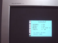
Connect the VGA (analog interface) cable from PC monitor to the existing connector. Power up the device using one battery or plugging it in one power adapter (avoid simultaneus powering situations). Using the first push button you can change the output video mode (resolutions) in a inner sequence. The second push button changes the video raster (image) in the same inner sequence. You can obtain any resolution-raster combination using the existing keys.
8. The component list
| Qty | Value | Parts | Remarks |
| 2 | 18pF | C1, C2 | |
| 1 | 100uF/16V | C3 | |
| 1 | 470uF/16V | C4 | |
| 3 | 470ohm | R1, R3, R4 | |
| 3 | 1K | R2, R5, R6 | |
| 1 | 10K | R7 | |
| 2 | BAT42 | D1, D3 | |
| 1 | DC Power Connector | J1 | |
| 1 | Power Switch | S2 | SKS06LP orderable from Schukat |
| 1 | VGA 15pin | U$1 | |
| 2 | Push Button | S1, S3 | High profile versions |
| 1 | 20.0000MHz | Q1 | Low or high profile |
| 1 | TS2950 | IC2 | LM2950 or 78L05 compatible |
| 1 | ATTiny2313 | IC1 | Non AT90S2313 compatible |
| 1 | Enclosure box | Box | LP6029B-SW (battery compartment included) orderable at Schukat |
9. Pictures

10. Download
software.zip Ver1.2 30.08.2007
hardware.zip Ver1.2 11.12.2006
11. A few remarks
It is not allowed to use this design for commercial purposes of any kind.
The autors take no responsability for any kind of losses or problems generated by this design.
There is no technical support offered for this project.
