Albert O’Grady
EDN
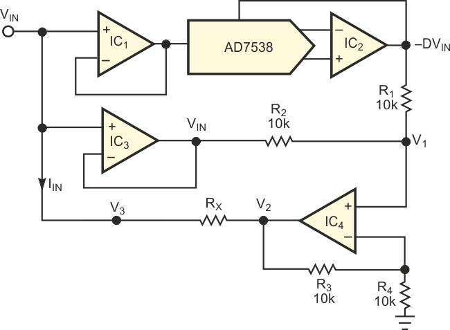
Figure 1 shows a configuration that implements a digitally programmable resistor using a quad op amp and a multiplying DAC. The circuit is equivalent to a voltage-controlled resistor. The simulated resistor has a value that reflects the ratio of a fixed resistor (RX) and a control voltage. Applications include generating precise resistance values for remotely controlling monostable multivibrators and configuring voltage-controlled loads in simulation circuits. The circuit provides linear control of resistance using the AD7538 14-bit multiplying DAC. You can obtain logarithmic control of the resistance by using an AD7111A logarithmic DAC as the voltage-control element.
 |
||
| Figure 1. | A multiplying DAC implements a linear, digitally programmable resistor. | |
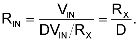
Analysis of the circuit in Figure 1 reveals the following:
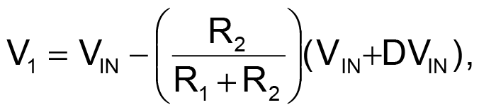
where D is input code to the multiplying DAC.
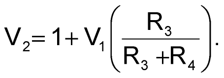
If R1 = R2 = R3, then
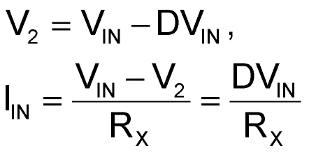
and
The circuit in Figure 1 operates as a voltage-controlled current source. You can adapt it for use as a basic functional block in the design of a biquad filter. In the adaptation, you modify the circuit to provide a voltage-controlled capacitor rather than a resistor.
