Catherine Chang, Philip Karantzalis and Aaron Schultz, Linear Technology
Design Note 564
Our op amp family has expanded with industry-leading speed versus supply current. The LTC6258/LTC6259/LTC6260 family (single, dual, quad) provides 1.3 MHz gain-bandwidth product at a super low 20 μA supply current, with 400 μV maximum offset voltage and rail-to-rail input and output. In combination with a 1.8 V to 5.25 V supply, this op amp enables applications requiring uncompromised performance with low power and low voltage at reasonable cost.
Utility sine wave
One does not expect to generate a sine wave with –100 dBc distortion using a 5 V low power op amp. All the same, a bandpass filter using the LTC6258 can combine with an easy-to-use low power oscillator to create a sine wave at low cost, low voltage, and extremely low dissipation.
Active filter
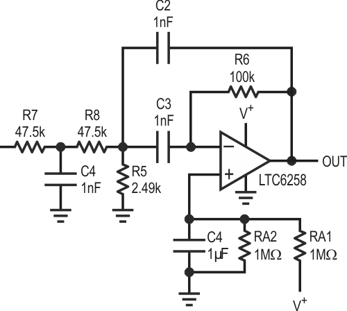
The bandpass filter of Figure 1 is AC coupled to an input. As a result, the LTC6258 input does not place a burden on the previous stage to develop a particular absolute common mode voltage. A simple resistor divider with RA1 and RA2 provides biasing for the LTC6258 bandpass filter. Pegging the op amp inputs to a fixed voltage helps to reduce distortion that might arise with moving common mode.
 |
||
| Figure 1. | 10 kHz Bandpass Filter. | |
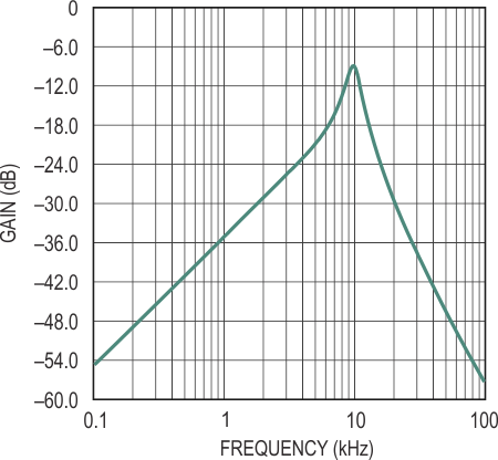
This filter is centered at 10 kHz (Figure 2). The exact resistance and capacitance values can be tweaked upward or downward, depending on whether lowest resistor noise or lowest total supply current is most important. This implementation was optimized for low dissipation by reducing current in the feedback loop. The capacitors C2 and C3 were initially 4.7 nF or higher, with lower resistor values. In the end, 1 nF with higher resistors optimized for lower dissipation.
 |
||
| Figure 2. | Bandpass Filter Gain/Phase vs Frequency. | |
Besides power dissipation, a secondary but no less important aspect of feedback impedance is loading of the op amp rail-to-rail output stage. Heavier loading, such as between 1 K and 10 K impedance, significantly lowers open loop gain, which in turn affects the accuracy of the bandpass filter. The data sheet suggests AVOL reduces by a factor of 5 from 100 kΩ to 10 kΩ. Lower C2 and C3 might be feasible, but then R6 becomes even larger, introducing more noise at the output.
The target Q of this bandpass filter is moderate – approximately 3. A moderate Q, rather than a high Q, allows for use of 5% capacitors. Higher Q will demand more accurate capacitors, and very likely higher open loop gain at 10 kHz than is available with the feedback impedance load. Naturally, moderate Q results in less attenuation of harmonics than a higher Q.
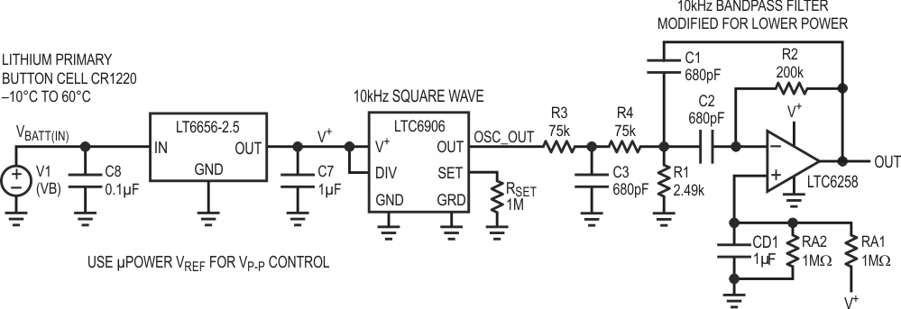
Adding The Oscillator
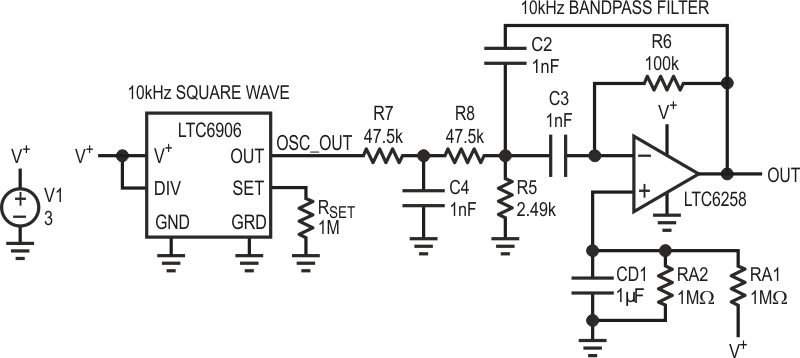
A low power sine wave generator can be derived by driving a square wave into the bandpass filter. A complete schematic is shown in Figure 3. The LTC6906 micropower resistor-set oscillator easily configures as a 10 kHz square wave, and can drive the relatively benign loading seen in the bandpass filter input resistors. Supply current of the LTC6906 at 10 kHz is 32.4 μA.
 |
||
| Figure 3. | 10 kHz Oscillator Circuit Using LTC6906 TimerBlox Input. | |
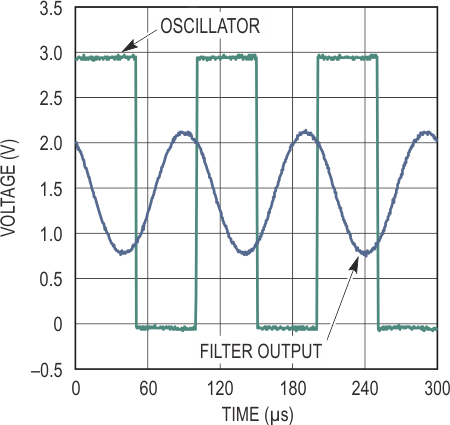
Figure 4 shows the LTC6906 output and bandpass filter output. HD2 of the sine wave is –46.1 dBc, and HD3 –32.6 dBc. The output was 1.34 VP-P to 1.44 VP-P with exact level varying slightly due to finite op amp open loop gain at 10 kHz. Total current consumption is below 55 μA on a 3 V rail.
 |
||
| Figure 4. | Voltage Waveforms Oscillator and Filter Output. | |
Other Enhancements
Figure 5 shows optional enhancements. A low power reference takes advantage of the ability of the LTC6906 and LTC6258 to operate on a very low supply. The reference provides 2.5 V from a battery input. The fixed 2.5 V supply stabilizes the output voltage swing in the presence of varying input voltage. In addition, even lower filter capacitor values with higher resistances reduce LTC6258 loading further, lowering dissipation and improving filter accuracy.
 |
||
| Figure 5. | Oscillator and Filter with a Regulated Supply. | |
Conclusion
The LTC6258/LTC6259/LTC6260 family (single, dual, quad) provides 1.3 MHz gain bandwidth at a low 20 μA supply current, with 400 μV maximum offset voltage and rail-to-rail input and output. In combination with 1.8 V to 5.25 V supply, this op amp enables applications requiring excellent performance with low power and low voltage at low cost.
