The Charger
Literature on the batteries is rather spotty. I learned enough to believe Li-Ion would work for me. The only thing I needed to do was find or build a charger. My first battery turned out to be from an AMS Tech Rodeo 7000 laptop - they sell an external charger for about $200. I searched Ebay and the Electronics supply houses for generic smart chargers but I could not find one that would handle my battery. There are chargers for under 1A around, but not for the big guys. I decided I would have to build one.
I considered four possible ways to build such a charge controller:
- Linear charger chips - simplest, inefficient, but no controller chips made for more than 2 cells.
- Switching mode chips - more complex, more efficient, Maxim and TI make controllers for up to 4 cells, surface mount only
- Smart Switching mode chips - the charge controller talks to the battery and the battery tells the charger what to do. The nice thing is that you do not need to know your batteries characteristics. These devices require about double the external device count compared to the basic switching mode chips and do not work with non-smart batteries. Surface mount only.
- Use a uC to control the charge - luckily Atmel published an App Note on this.
My first attempt at this was based on the MAX745 from Maxim, a non-smart switching mode device. One problem with these chips is that they are available in surface mount only - they are designed to go in cell phones and laptops remember. The other problem was, that despite much trying, I was never able to get a charger working properly. I finally got one to the "sort-of-works" point but it still took some hand waving and nose pointing to get it started sometimes.
Atmel then published App Note AVR450 describing how build a universal charger for Ni-Cads, NiMH, SLA and LiIon batteries based on a AT90S4433 microcontroller. This seemed to be the answer and is what I used as the basis of this design. I modified it considerably, added the Smart Battery interface (which necessitated upgrading from an AT90S4433 to an ATMEGA8) and added preset and adjustable battery parameters. I substituted available transistor, MOSFET, Schottky diodes and coils for those specified and it all worked pretty much from the get go.
The Project
The article now describes how to build a charger controller board and how to program the AVR microcontroller. You should have a LiIon battery you can practice on - my practice battery is still alive and well despite considerable abuse. The more you know about the battery the better: Maximum charge voltage and amps (sometimes printed on the case), thermistor (yes/no and resistance - they are not always 10K) and Smart Battery or not.
In addition to the charge controller a DC supply capable of providing at least 2 volts more than the max cell voltage (14.6 volts in my case) at the desired current is required. At the capacities I want you are out of the "Wall wart" category. I found a laptop supply for a Dell rated at 18V @3.5A.
The board is fabricated using easily obtainable components - refer to the parts list in the Atmel App Note. I made some substitutions and marked the schematic up accordingly.
The ATMEGA8 is a new release and has 8K Flash, 1K RAM in a 28 pin narrow DIP package and can be clocked up to 16MHz. If you are willing to eliminate the Smart Battery interface and delete some of the debug code the code could be made to fit in an AT90S4433 as per the original Atmel design.
The microcontroller software used is GCC version 3.2. This version is required to accommodate the direct I/O assignments that resulted from the conversion from IAR that was used in Atmels App note. The software is actually a combination of Atmels, converted from IAR, an I2C interface, converted from 68HC11/Imagecraft and my own GCC code. As a result the program does not read as well as I am used to as 3 different styles are evident.
The current / voltage control is managed by a PWM output into a P-Channel MOSFET. A large inductor / capacitor combination is used to stabilize the circuit. The special purpose chargers generally run at much higher frequencies ( 150KHz compared to 15KHz) and can thus use smaller components, not that important in my case.
The charger provides a continuous data stream output from the UART for your PC. I send initialization info and continuous charge status information from the charger, and, if a Smart Battery is connected, the battery, that can be viewed on a PC terminal program. Baud rate is set at 115K but could be lowered as desired.
The charge LED flashes quickly during constant current mode, slower during constant voltage mode and ends up at steady on when charging has completed.
The charger was operational after a weeks part time effort, another few days were spent on the Smart Battery interface and a couple more to document the whole thing.
The Hardware
For one-off projects such as this I prefer to use wire-wrap in combination with soldering. I use a foil grid one side board with foil down:
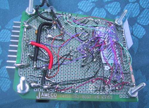
I spot solder most components to the grid and use wire-wrap to wire it up. This board had a requirement for larger power wire which was installed where needed. Notice from the photo that I use homemade wirewrap pin labels - I print them on the printer and push them down over the pins. Works quite well. I also print out top of board ID labels. This project would be a good candidate for a printed circuit board - I just don't have any incentive now that my board is working.
There are three schematics that describe the board:
Click to enlarge
The microcontroller itself
Atmel designed charge control circuitry
Atmel designed reference voltage circuit
The microcontroller physical design is pretty much a standard AVR design. A 7.3 MHz crystal is used (the ATMEGA8 can take up to 16 MHz). I added an 8 point dip switch for battery parameter selection and a variable resistor for setting Charge current in "Custom" mode. I include a UART interface but did not install the RS-232 interface on the board as I have a very useful cable with a MAX233 built in.
You can see from the photo that I have attached a heat sink to the HexFET. I suspect I could get up to 3.5 to 4 amps without problems with this setup. So far I've held back to 2.5 amps as I have no spare HexFETs in house and don't feel like doing destructive testing. Read the App note for a good description of how this circuit works. I mounted the power components on the opposite end of the board from the uC and kept three separate grounds (uC, analog, charger power) connected only at a single point. The op amp circuit used to measure battery voltage and current will take a little fiddling around. You do not need to have exact values as the circuit can be calibrated using software. Refer to the App Note for determining your specific resistor and calculating the inductor size. Here is an Excel calculation worksheet.
In case you are unable to get the thermistor operational I have a provision to jumper in a 10K resistor and bypass the protection. Obviously this should be a last resort. I may need to install several jumper selectable thermistor inputs as there seems to be a wide range of resistance ranges in use.
I use a standard power jack for the power supply connection and at the battery. In addition I have a separate 3 circuit cable to connect to the thermistor and Smart Battery lines at the battery. The actual battery connectors are very specific and not easy to find. I found one for my first battery but not for the Gateway. You will likely have to fab something up yourself.
To be continued
