Vasile Surducan and Emanoil Surducan, National Institute for R&D of Isotopic and Molecular Technologies, Cluj-Napoca, Romania
Multiplex IO lines and drive LEDS without ghosting.
Digital-I/O-multiplexing techniques, such as “Charlieplexing” or “Gugaplexing,” let an eight-digit, seven-segment LED display connect to nine I/O pins of a microcontroller (references 1 and 2). These methods use lower-duty-cycle timing, which requires a driver between the microcontroller’s I/O lines and the display to achieve good visibility. The circuit in Figure 1 uses an 8+N/2 I/O bus for interfacing an N-digit display and as many as eight buttons on the same bus. This method needs no driver. You can apply it to any programmable device with LED-driving capabilities, such as small PIC or Atmel microcontrollers.
.gif)
Figure 1. Common-anode and common-cathode LED displays can connect to the same bus
In Figure 1, R8 is a segment current-limiting network resistor for the IC1 common-anode LED display and the IC2 common-cathode LED display.
Any combination of standard and superbright displays for this IC1/ IC2 pair is acceptable with proper duty-cycle timing adjustment in firmware. The R7 network and D1 to D8 switching diodes act as antighosting devices. “Ghosting,” or faint illumination, is the partial illumination of the segments, which should be in an off state, as a result of switching glitches or unsuitable voltage levels on the driving pins when those pins are in a high-impedance state. Ghosting results from using all the microcontroller’s I/O: output-high, output-low, and high-impedance logic levels, switching between them in an infinite-loop sequence (Table 1). The following equation calculates the value of R7: R7=(VSAFE−0.6V)/10IGHOST, where 0.6V is the voltage drop of diodes D1 through D8 at 25°C, IGHOST is the threshold value of the static-leakage current for which the ghosting effect is visible but minimal, and VSAFE is the voltage potential value that may appear on any segment when the segment is not illuminated.
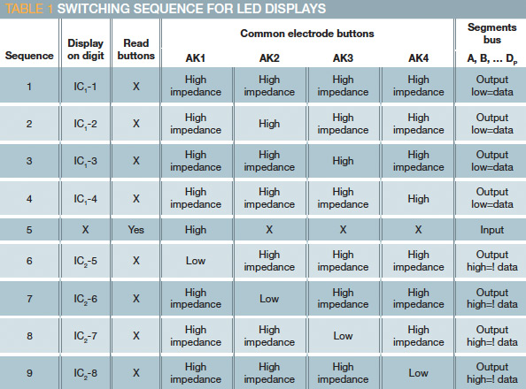
You can experimentally find IGHOST at an ambient-light level of less than 10 lux by injecting a small current into a separately powered digit segment and observing the current value and segment voltage drop at the moment when the segment begins to light up. For a superbright display, IGHOST should be approximately 70 μA. The IGHOST current creates an unwanted voltage drop on the segment LED, VGHOST: VGHOST=1.54V and VSAFE≤kVGHOST, where k, a factor of confidence, ranges from 0.5 to 0.7, compensating the VGHOST dispersion of displays. In this example, VSAFE is 0.7V for a superbright LED display and 1V for a standard display. If you combine normal and superbright display types, choose the smallest VSAFE for the computed value of R7.
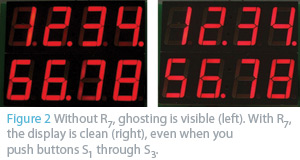
Increase efficiency in embedded digital-I/O lines figure 2Reading electrode buttons is an asynchronous procedure, unlike digital multiplexing; thus, any combination of button presses must not turn on any segment of IC1’s or IC2’s digit group. R1, R2, and R3 limit the current through IC1 segments below IGHOST when Q1 is on and AK1 is at an output-high level. R4, R5, and R6 polarize Q1; R6 keeps Q1 off even when AK1 is in a high-impedance state; and R4 limits the Q1 collector current. Note that the weak pullup of the A, B, and C microcontroller inputs is on during the button-reading sequence. You can download the firmware source for the PIC16F886 driving the display in Figure 1 here. Adding R7 and D1 through D8 eliminates ghosting (Figure 2).