Vishwas Vaidya
Edge-triggered interrupts are useful in microcontroller (MCU) applications for processing asynchronous events like switch closures, level transitions, and pulses. However, low-cost MCUs offer limited on-chip resources to handle such interrupts.
Yet designers can “trick” an unused on-chip UART into interrupting the MCU to detect edges in the input waveform. This concept avoids the need to upgrade to a more costly MCU when all the conventional on-chip resources for edge-triggered interrupts have been exhausted but the application needs to process one more edge-driven input.
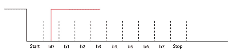
In this scheme, the Rx pin of the asynchronous receiver acts as the edge-driven interrupt pin. When the Rx pin receives a high-to-low transition (that is, a low-going edge in the input signal), the UART interprets this as the arrival of a start bit.
The baud-rate clock goes on sampling the input and senses a byte value of 0x00 with a “break error” bit set. The error is caused by the absence of the stop bit in the input waveform, since the input voltage level is still logic zero when the UART expects a stop bit.
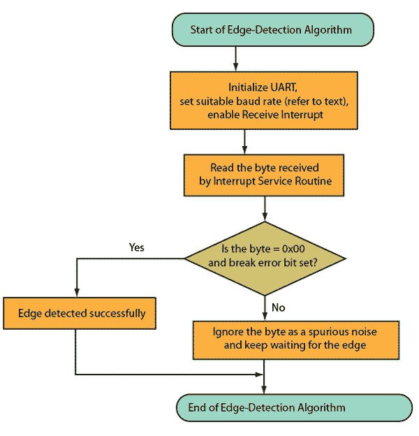
The Interrupt Service Routine detects this “zero byte with break error” and signals to the application program regarding edge detection in the input waveform. The baud-rate should be high enough to minimize the latency involved in the edge detection but low enough to filter-out, or debounce, spurious noise disturbances.
 |
||
| Figure 1. | The falling edge marks the arrival of the start bit for the UART. If a rising edge is received before the stop bit (red line), it is interpreted as a spurious glitch input and the byte is ignored. | |
This way, if a spurious noise glitch interrupts the controller, the input will return to a logic high before the baud-rate clock finishes reading a byte (Fig. 1). The Interrupt Service Routine will now detect a “non-zero byte” without any error. The application routine (Fig. 2) can recognize this as a spurious glitch and ignore it.
|
|
||
| Figure 2. | The flow-chart shows how UART-based edge detection works. Note that if b0 through b7 is zero and the break error bit is set (logic zero), the edge will be detected. | |
To detect a positive rising edge, simply add a transistor inverter to the input to create the desired falling edge.
