Some time ago we have posted alphanumeric AVR-GCC LCD library. It works fine in 8-bit and 4-bit modes. But it has some limitations that some people may find annoying. One of them is requirement that LCD pins has to be byte aligned for instance in 8 bit mode LCD_D0 … LCD_D7 pins has to be connected to AVR single AVR port. Similar situation is with 4-bit mode where LCD data pins has to be connected to single port 4, 5, 6 and 7 pins. For both modes control pins RS, RW and E has to be connected to single port.
And this is how most LCD libraries work when you try to look for one in the internet. In reality things may be a bit different each microcontroller pin has at least several alternative functions available like ADC, INT, I2C, USART and if project requires using one or another and you still need LCD standard libraries won't work as most likely you wont be able to get all particular port pins connected to LCD. You gotta use whats left. This is why I decided to find a little time and modify LCD library to support these cases. Didn't want to write everything from scratch or change its functionality – just wanted it work with existing projects but have more freedom with new ones. So basically I left standard 8-bit and 4-bit same. The main change is adding two more modes: 8-bit mix and 4-bit mix. These modes allow connected LCD to any free pins of microcontroller.
Configuring LCD for 4-bit mixed pin mode
Lets look what you need to start using these features. We can do this by selecting a simple example. This time 4-bit mixed mode:
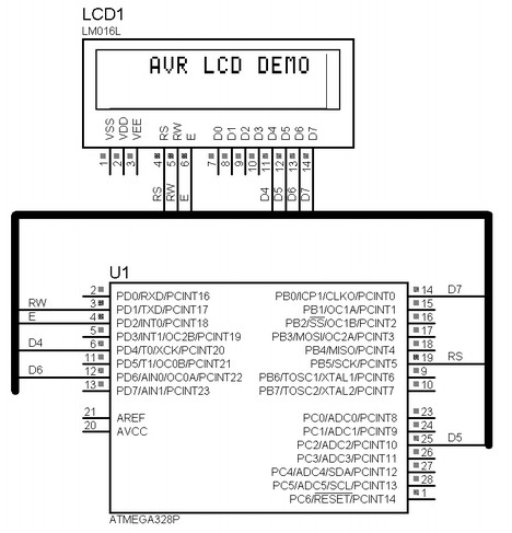
As you can see LCD pins are connected to Atmel Atmega328P in following way:
RS → PB5
RW → PD1
E → PD2
D4 → PD4
D5 → PC2
D6 → PD6
D7 → PB0
So we get unaligned situation. Firs of all we need to edit pin assignments in lcd_lib.h. First of all uncomment one of following defines that indicate the mode chosen.
So we get unaligned situation. Firs of all we need to edit pin assignments in lcd_lib.h. First of all uncomment one of following defines that indicate the mode chosen
//LCD 4 bit interface is used (single port pins)
//#define LCD_4BIT
//LCD 8 bit interface is used (single port pins
//#define LCD_8BIT //LCD 4 bit interface is used (mixed port pins)
#define LCD_4BIT_M
LCD 8 bit interface is used (mixed port pins)
//#define LCD_8BIT_M
This time we use LCD_4BIT_M
Then we need to associate LCD pins with port pin numbers. If LCD_RS is connected to PB5 pin then we write 5:
#define LCD_RS 5 //define MCU pin connected to LCD RS
#define LCD_RW 1 //define MCU pin connected to LCD R/W
#define LCD_E 2 //define MCU pin connected to LCD E
#define LCD_D0 0 //define MCU pin connected to LCD D0
#define LCD_D1 1 //define MCU pin connected to LCD D1
#define LCD_D2 2 //define MCU pin connected to LCD D2
#define LCD_D3 3 //define MCU pin connected to LCD D3
#define LCD_D4 4 //define MCU pin connected to LCD D4
#define LCD_D5 2 //define MCU pin connected to LCD D5
#define LCD_D6 6 //define MCU pin connected to LCD D6
#define LCD_D7 0 //define MCU pin connected to LCD D7
And now we have to define port and data direction register for each pin. As pins may be connected to different ports – we need to work with individual pins. We edit this part:
#ifdef LCD_4BIT_M || LCD_8BIT_M //8- bit or 4 - bit mode
#define LDPRS PORTB //RS pin assignment
#define LDDRS DDRB
#define LDPRW PORTD //RW pin assignment
#define LDDRW DDRD
#define LDPE PORTD //E pin assignment
#define LDDE DDRD
#define LDPD0 PORTD //D0 pin assignment
#define LDDD0 DDRD
#define LDPD1 PORTD //D1 pin assignment
#define LDDD1 DDRD
#define LDPD2 PORTD //D2 pin assignment
#define LDDD2 DDRD
#define LDPD3 PORTD //D3 pin assignment
#define LDDD3 DDRD
#define LDPD4 PORTD //D4 pin assignment
#define LDDD4 DDRD
#define LDPD5 PORTC //D5 pin assignment
#define LDDD5 DDRC
#define LDPD6 PORTD //D6 pin assignment
#define LDDD6 DDRD
#define LDPD7 PORTB //D7 pin assignment
#define LDDD7 DDRB
#endif
This is practically it. We can start using LCD as we did in old library version.
Part 2 - Configuring LCD for 8-bit mixed pin mode