This Design Idea shows how to calculate the inductance of a multilayer air-core coil using only its dimensions and resistance. If you know the dimensions and the number of turns on an air-core coil, you can easily calculate the inductance. With the dimensions in millimeters, the inductance, L, in microhenries is a function of the square of the turns, as the following equation shows:

where D is the average diameter of the coil; h is the height of the coil; and g is the depth of the coil— all in millimeters ( Figure 1 ).
 |
|
| Figure 1. | You can calculate the inductance of a coil if you know its dimensions and number of turns. |
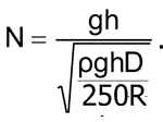
If you don’t know the number of turns, you can still calculate the inductance using the dc resistance of the coil. For this technique to be accurate requires tight and regular coil winding using enameled cylindrical wire (Figure 2). You could use the wire dimensions to give an approximate expression for the total number of turns, N:

where d is the diameter of the wire, but this Design Idea assumes that the wire diameter is unknown.
 |
|
| Figure 2. | You can estimate the inductance of a tightly and regularly wound coil from its dimensions and resistance. |
Because the length of an average turn is equal to π×D, the total length of the wire is (N ×π×D). The square of the cross-sectional area of the wire is

You can express the resistance, R, of the coil as

where ρ is the wire resistivity in ohmmeters and the resistance is expressed in ohms. Thus, you can derive an expression for the wire’s diameter squared:

You would then substitute for the d term in the expression for turns:

You can now square both sides of the equation and cancel terms:

.
Substituting the value of N2 into the first equation yields

Using the value of ρ for copper wire, you get an expression for L, which depends only on the resistance and the physical dimensions of the coil:

L and R are proportional to each other yields, yielding two interesting consequences. First, for a series RLC circuit, the following equation defines the damping factor, ζ :
ζ=R/2×√(C/L),
meaning that the damping factor is proportional to the square root of R for a given C and coil dimensions D, g, and h. Second, the quality factor, Q, of a coil with given values of D, g, h, and ρ and an angular frequency of w=2πF is a constant value:
