Contemporary research laboratories include a variety of instruments that connect using any of several interface methods to a PC for automating procedures and collecting data. Although different communication interfaces exist, the GPIB (general-purpose-interface bus) still enjoys wide popularity. The host PC must include a suitable GPIB controller—an internal interface card or an external device. Newer PC designs are phasing out traditional internal buses, such as PCI, ISA, and EISA, in favor of other standards, so using an external controller offers a more appropriate approach because external I/O ports, such as RS-232 and USB, tend to maintain backward compatibility.
This Design Idea covers the development of a GPIB controller, which turned out to be easier and cheaper than commercially available alternatives. The design uses easy-to-obtain components with a total component cost of approximately $ 50. For comparison, a commercial controller costs at least 10 times more: $ 500 to $ 1000. The USB 2.0-compliant controller, an external device, draws its operating power from the bus and provides plug-and-play operation and high-speed data transfer. In addition, a USB-controller design extends its applications to notebooks and other computers that lack available I/O slots. The controller resides on a double-sided pc board and fits into a 123 × 30 × 70-mm enclosure (Figure 1). To simplify controller use, the design uses National Instruments' (www.ni.com) LabView graphical programming language to develop the appropriate driver.
The design uses the FT245BM USB-controller IC from Future Technology Devices International Ltd (www.ftdichip.com), which features an 8-bit parallel connection to the host microcontroller and a virtual-communications port to the PC-interface side. The circuit operates at a full speed of 12 Mbps. Targeting use in GPIB applications, the 75160 and 75161 ICs drive GPIB I/O lines. An Atmel (www.atmel.com) AVR AT90S8515 microcontroller provides firmware-resident sequence control and in-circuit-programmable flash memory that simplifies firmware design and upgrades. The USB also can supply 5V of power at as much as 500 mA, which eliminates the requirement for an external power supply. The controller also supports the required low-power mode to reduce consumption to less than 1 mA.
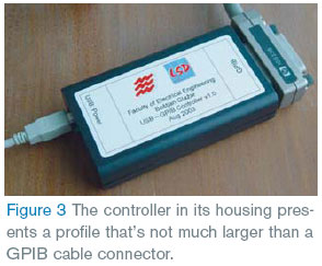
The designers used the Protel (www.altium.com) schematic-capture and pc-board-layout software to design the circuit. They used a milling machine to produce the prototype pc board and partially assembled the board with a manual SMD placer. You can also use a commercial prototype pc-board-fabrication service to prepare a double-sided pc board with plated through holes and manually assemble the circuit. Figure 2 shows an internal view, and Figure 3 shows the completely assembled controller, which is easy and fast to build.
The controller communicates with the host computer through a logical serial interface that enables use of the controller with any programming language that supports serial-port communications. The LabView driver is compatible with LabView's built-in GPIB driver, thus simplifying adaptation of programs to the new interface. The driver is a collection of virtual instruments, which require only one more input—that is, a serial-port number—than a built-in GPIB driver.
Thanks to its open-source design, the controller provides a highly cost-effective approach to controlling GPIB instruments that's adaptable to many computational platforms. You can obtain the microcontroller's firmware; descriptions of the protocols; and all other necessary files, including a pc-board layout, at https://www.rlocman.ru/i/File/2008/01/22/gpib.htm. With that information, you can write a driver for whatever operating system or programming language you choose. In addition, the Web page includes firmware for the Atmel AVR microprocessor, a user's manual for the assembled interface, and additional notes on GPIB and LabView. To download a 1505-kbyte, zip-formatted archive containing the entire project, go to: https://www.rlocman.ru/i/File/2008/01/22/complete.zip.