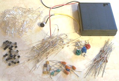
Here is a new version of the classic color organ, where different color lights are triggered by different frequencies of sound, resulting in a display that flashes along to music. In this case the newer type high intensity LEDs (3000 - 5000mcd) were used along with a very simple discrete transistor drive circuit. The design goals included small size and excellent portability, as well as long battery life. To begin, the required parts were gathered up. This included 49 each 3mm LEDs of various colors, a bunch of 1/8 watt resistors, some tiny salvaged transistors, a microphone, some trimmer potentiometers from a dead CRT, a 4 "AA" cell battery case with power switch, and a few small capacitors and diodes. The plan was to attach the LEDs and electronics to the front of the battery case, forming a compact unit that could be placed on a table or clipped to a shirt or jacket.
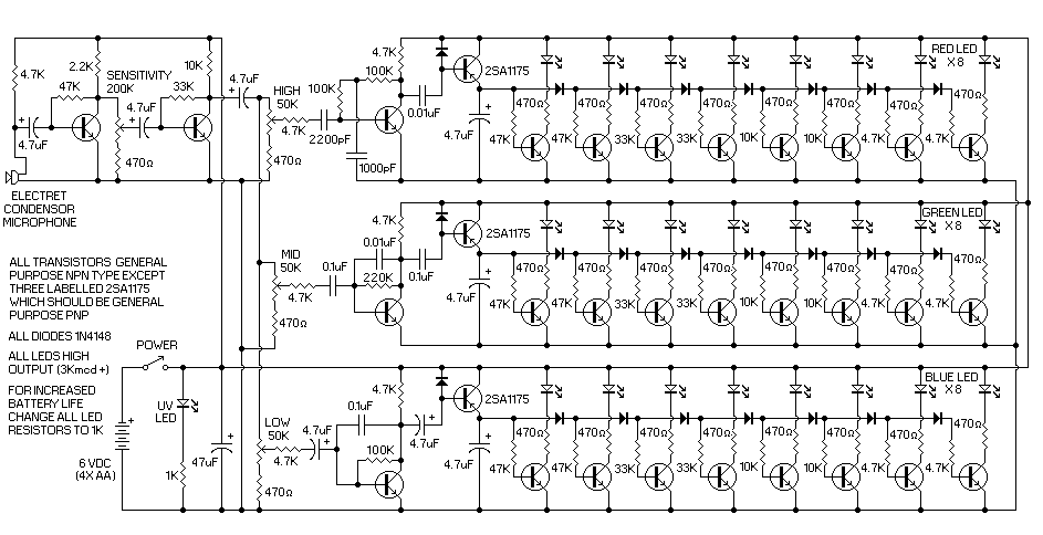
The circuit was designed to use common values of parts that are most easily available in smaller sizes. Ceramic and tantalum capacitors, 1/8 watt resistors, and small package semiconductors were chosen to conserve space. Integrated circuits were rejected as being too large for the 6 cm X 6 cm allowable space for circuitry and LEDs on the face of the battery case. The circuit itself consists of an electret condensor microphone feeding a two stage preamplifier with a sensitivity control. The signal is then split up into three channels with individual level adjustments. Each channel has it's own filter circuit, so that they each respond to a different range of sound frequencies, one each for treble, midrange, and bass sounds. The signal is then sent to an LED bargraph ladder circuit, with red/yellow, green/white, and blue/green leds for each channel respectively. Two LEDs were used for every one shown in the diagram, and the LED resistors were increased to 1K to extend battery life. With high output LEDs there is still lots of brightness even at lower currents, so this works well to lower current consumption. As well, there was a single purple colored UV LED included that is on whenever power is turned on.
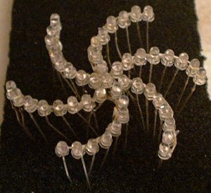
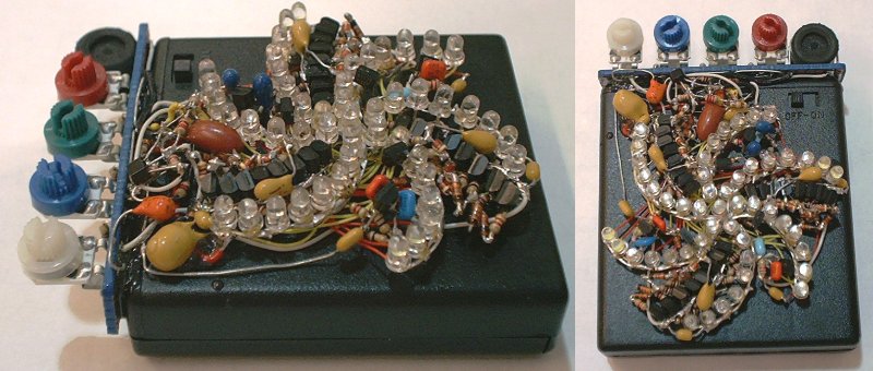
The 49 LEDs were soldered together in a spiral pattern with the UV LED in the center and three pairs of different colored LED spiral arms.
Next, the bar graph ladder circuits were built up from parts and inserted in spaces between the LED spiral arms.
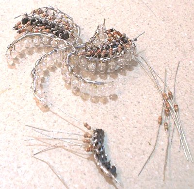
Here you can see all the ladders in place and the opposing LED arms wired across with wire-wrap type wire (does anyone use wire-wrap anymore??) Because this circuit was intended to be potted in epoxy, all connections were soldered. All of the circuitry constructed at this point is wired up and tested before the next step.
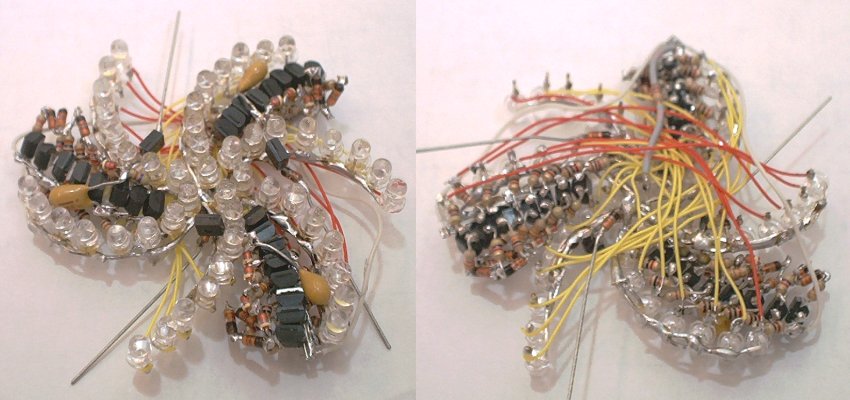
The filter circuits were then assembled and inserted in the remained spaces between the LED arms. A small circuit board to mount the microphone and trimmer potentiometers was also constructed. Everything is tested again.
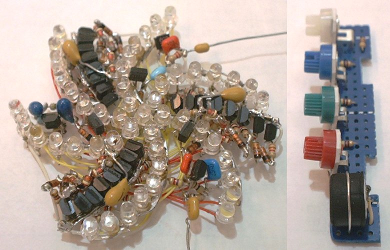
The circuit assembly and circuit board were then positioned on the front and top of the battery case and attached with a few spots of epoxy. The preamp circuitry and the rest of the wiring was then completed. Final testing was done and any problems resolved.
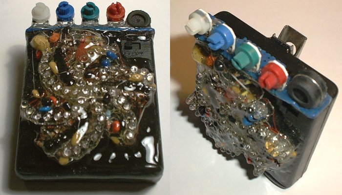
Finally, the fully tested and functional circuitry is encapsulated in epoxy. The project is completed by attaching a mounting clip to the back and adding glue to the bottom so that the case stands up firmly at the correct angle.
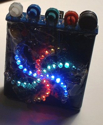
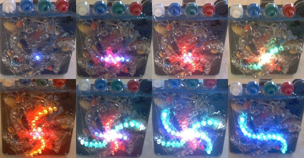
The finished color organ in operation. The project was a complete success, and should be a lot of fun at concerts and parties. A fresh set of batteries lasted for over three long nights of use, which is excellent. The way the different LEDs appear to dance to the music is great to watch and unfortunately cannot be seen with just the pictures shown here!